WHAT CAN WE DO FOR YOU?
Are you a structural engineer who needs general arrangement drawings (plans, sections, elevations or structural details)? Are you an architect who needs assistance with planning drawings or wants a digital 3D model to impress your clients? Do you need someone to draw up your drainage layouts, road layouts or reinforced concrete details? Would you like your hand-drawn sketches translated into first-class computerised drawings in 2D, 3D or both? Are you an estate agent who needs 2D or 3D floor plans, or a property developer who needs 3D visualisation services to showcase a property before it's even been built? Maybe you're a landscape and garden designer that needs assistance with 2D CAD and 3D visualisation? There are so many applications for computer aided design. GCCAD is here to help.
Below is a list of our services. Please click on the service you're interested in for an in-depth breakdown. Alternatively, please scroll down the page for further information and frequently asked questions.
OUR SERVICES


FURTHER INFORMATION
Using state-of-the-art 2D & 3D software, GCCAD provides quality CAD support for businesses and individuals. We are happy to work on all projects, of varying size and scope. We provide an overall quote before any work has commenced, to ensure you won’t receive any unexpected expenses when the work is invoiced. GCCAD understands that the design stage of any construction project is a back-and-forth process, so any corrections or minor amendments that are required after the work has been invoiced are provided free of charge; major amendments (such as changes to the original design) may be chargeable. Typically, we provide drawings “unbranded” but we can also create a template with your company logo (or use an existing template provided by you).
All we need from you is the project information. This could be provided in the form of a quick sketch or specified in the body of an email. For instance: structural engineers would provide sizes and specifications of the structural elements (such as beam sizes, floor spans, foundations etc), as well as a plan (either a dimensioned or to-scale sketch, or an architect’s drawing) for us to work from. From this, we can generate general arrangement drawings and a set of standard structural details. To work with architects, we would need a dimensioned or to-scale plan / sketch based on your site survey information, and a specification of materials, finishes (etc). From this we can generate full 3D models, which can then be used to create multiple 3D views, videos, interactive walkthroughs, plans, elevations & sections. When we have finished our work, we will email it to you in DWG / PDF / JPG format, or in the case of larger files (3D) we can provide easy, secure links for you to download the project files. Essentially, instructing GCCAD to create your 2D drawings and 3D models could save your business precious time & money, and allow your company to offer exciting new services to your clients. GCCAD can be contacted via email, contact form or telephone to discuss your project in more detail.
DISCLAIMER - Please note that GCCAD provides CAD & BIM support only and is not a registered Structural / Civil Engineer or Architect. All work undertaken by GCCAD must be checked & approved by an Engineer or Architect (individual or business) with the necessary Professional Indemnity Insurance, and submitted under your own company name. GCCAD does not submit work under its own logo and cannot accept responsibility for any misappropriate use or submission of the work we provide. All work shown on this website is for advertising purposes only.
FREQUENTLY ASKED QUESTIONS
Q: Can you produce work in Autodesk Revit?
A: Yes! We are conversant with Revit and have produced several models with it in the past. However, please note that GCCAD does not possess a commercial Revit license at this time; any work undertaken in Revit would require our client to provide us with a legal sign-in license. See the images and brief descriptions below for two example Revit projects built by our Senior Technician, Glen Cooper. The images show the projects across varying stages, from early design to final renders. Click an image to enlarge, then click on the right of that image to move on to the next.
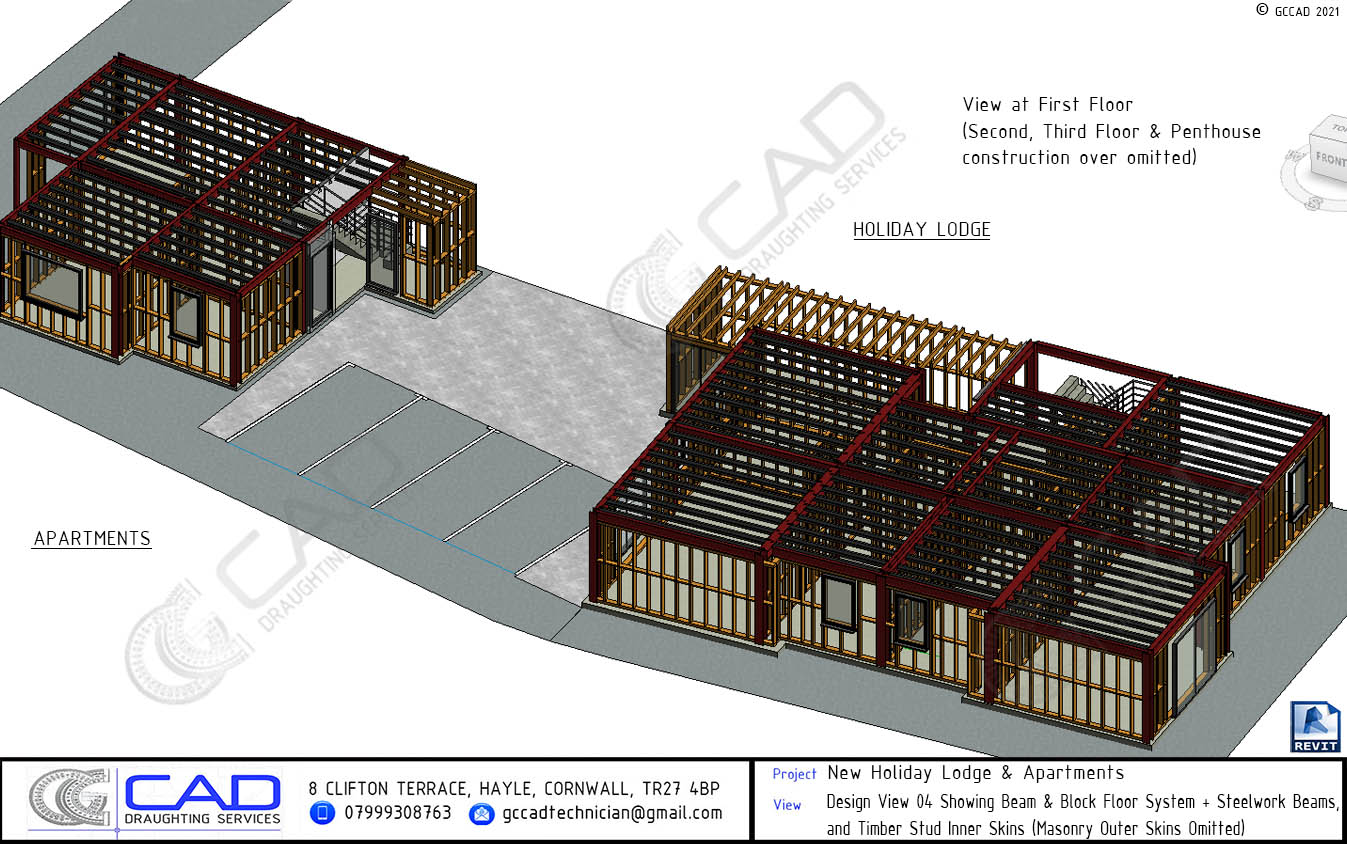
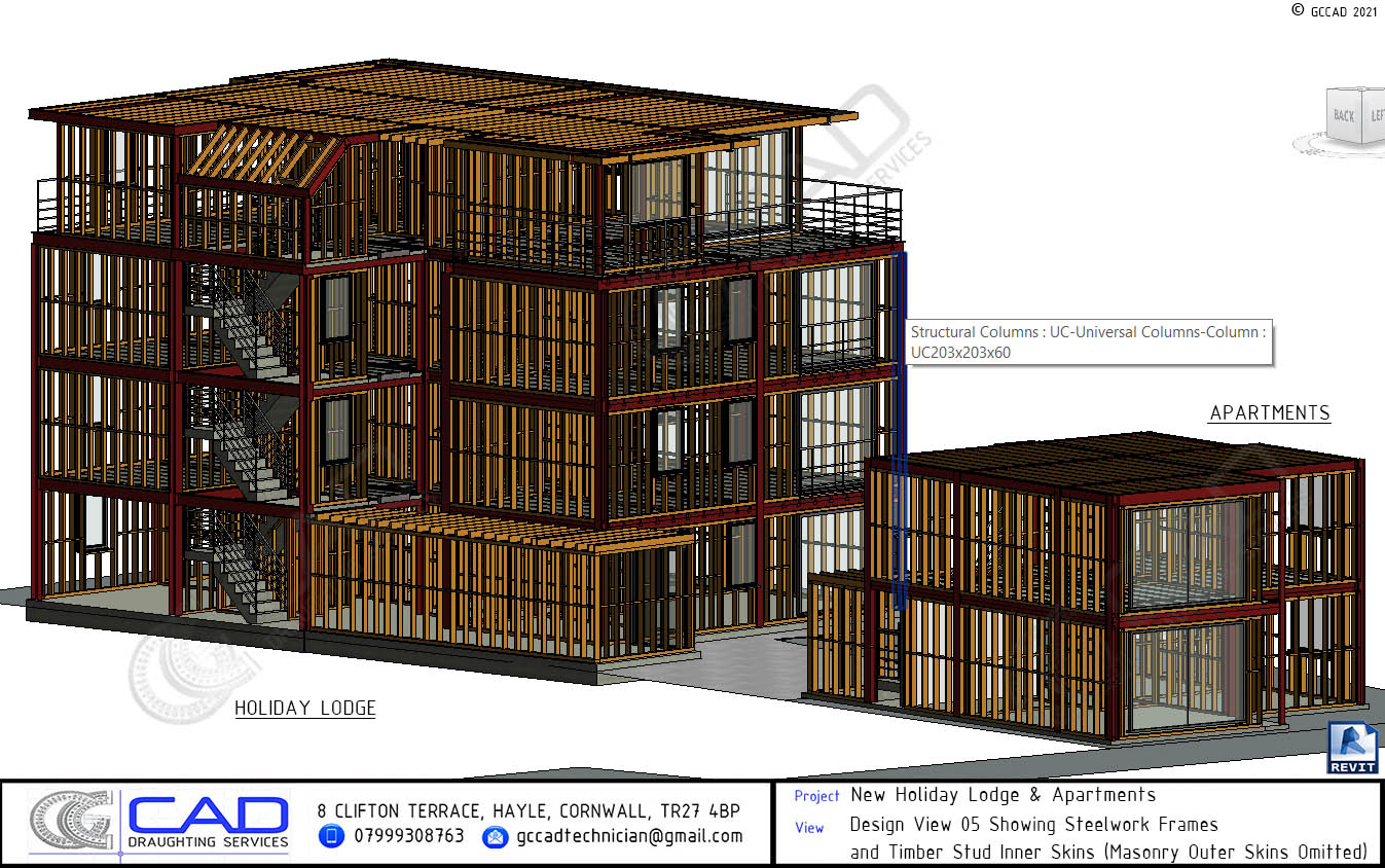
REVIT Project Example No. 1: New Holiday Lodge & Adjacent Apartments

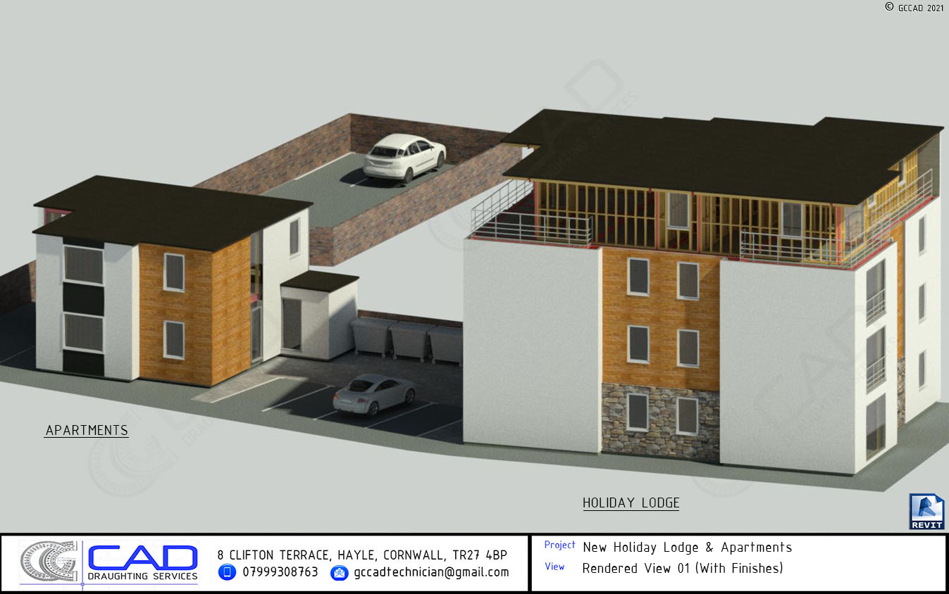


For this fantastic project, comprising a luxury holiday lodge and adjacent apartments, Glen built a highly detailed Revit model that demonstrates an effective combination of both architectural and structural elements. A basic representation of the external works was also presented, including front and rear parking, herringbone pavers, bin storage area and a reconstructed brickwork boundary wall.
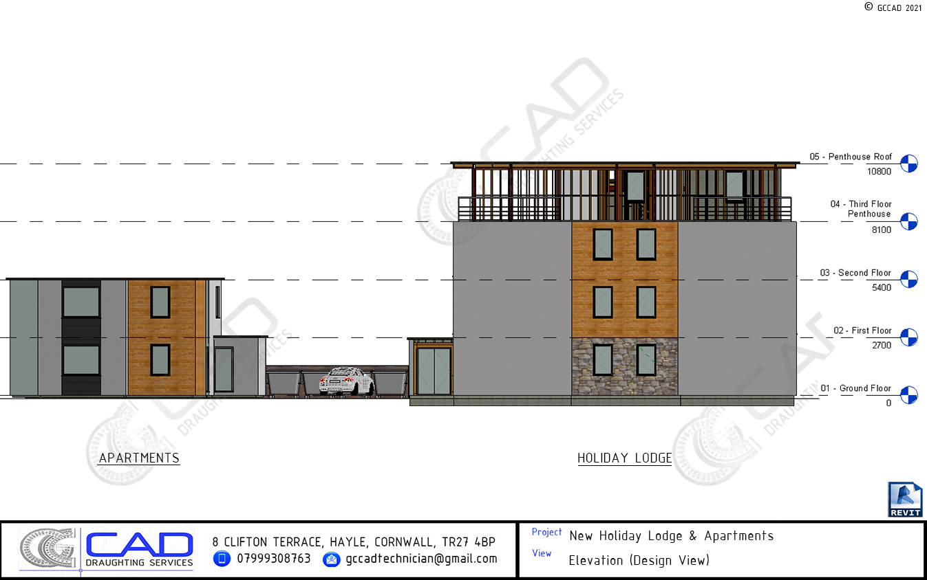

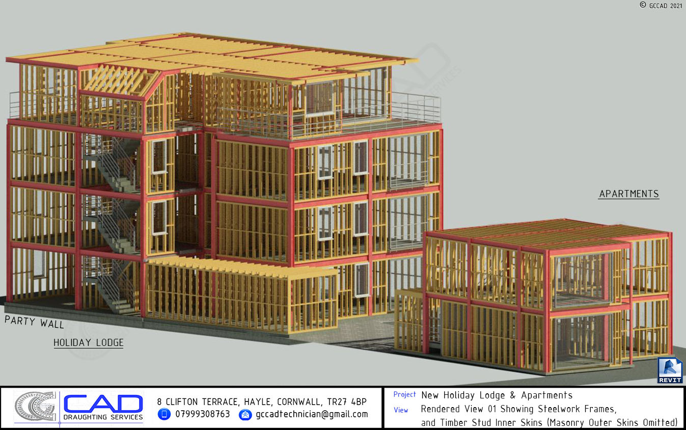
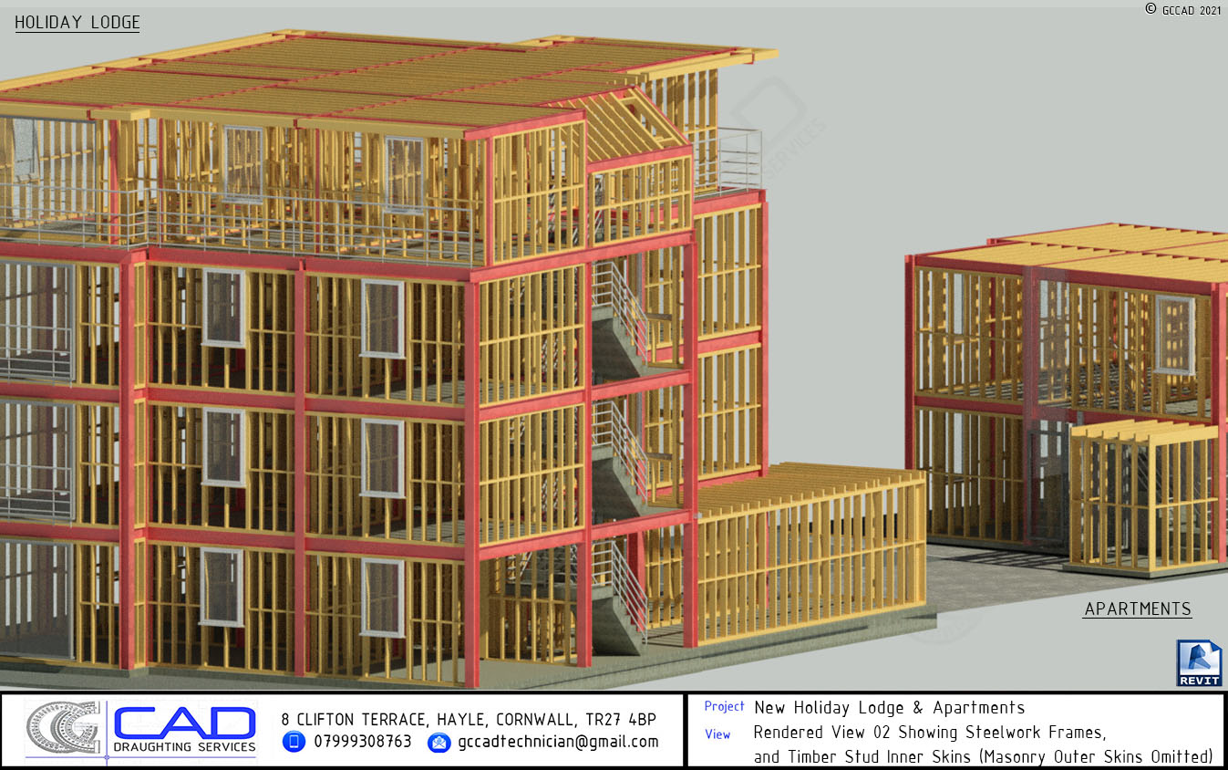
Architecturally, the following finishes are represented: white painted smooth rendered walls, dark grey zinc cladding (apartments only), shiplap cladding, natural stone (lodge only), light grey powder coated aluminium door and window frames, toughened laminated glass panels for penthouse level balustrades, main stairwell, and balcony doors (above ground floor level) all with stainless steel handrails, powder coated dark grey aluminium capping and single ply roofing membranes as flat roof coverings. Rainwater goods and finishes to the ground floor slab and beam & block floors (above ground floor level) are not present in the model as these were yet to be determined. Mineral wool insulation between the studwork was omitted for purposes of clarity.
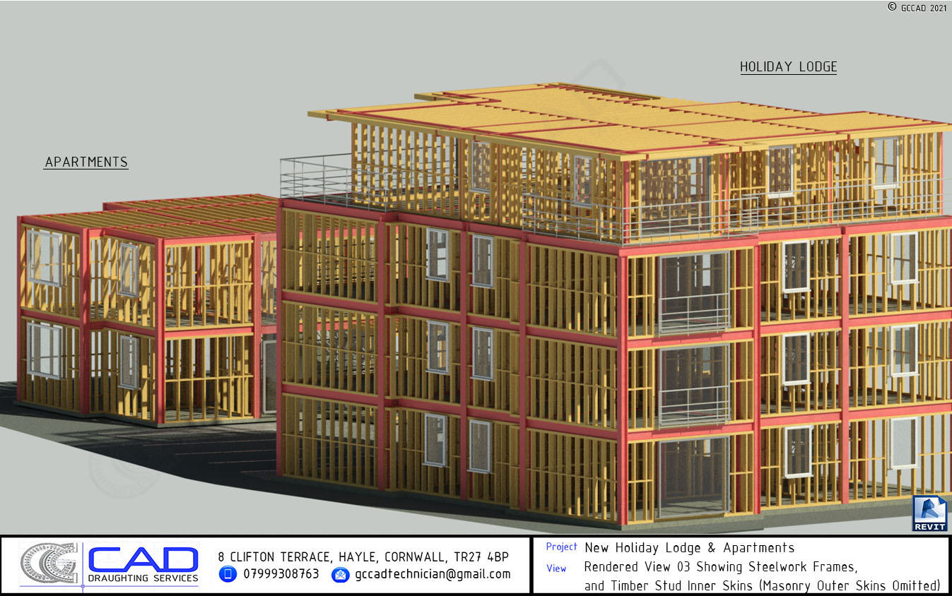
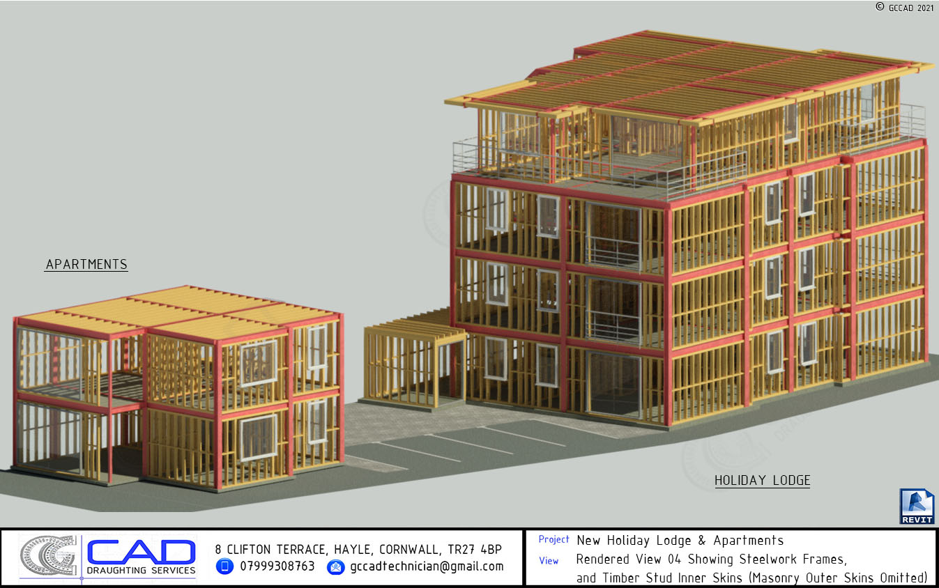

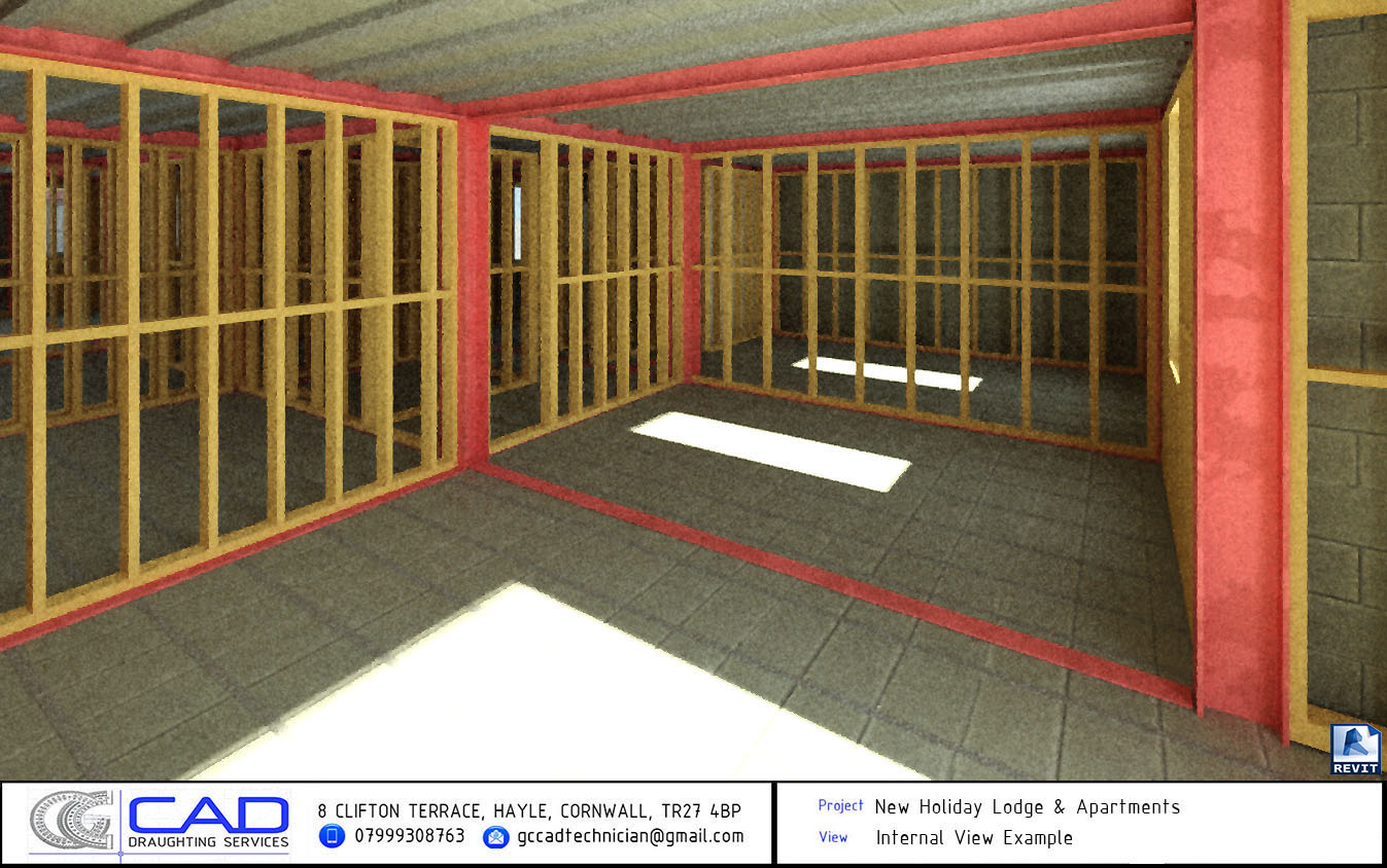
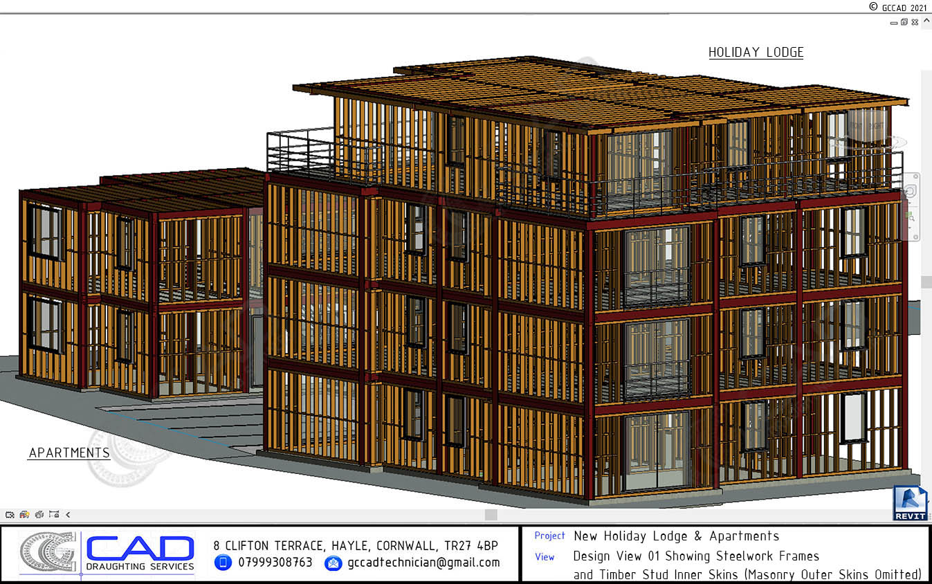
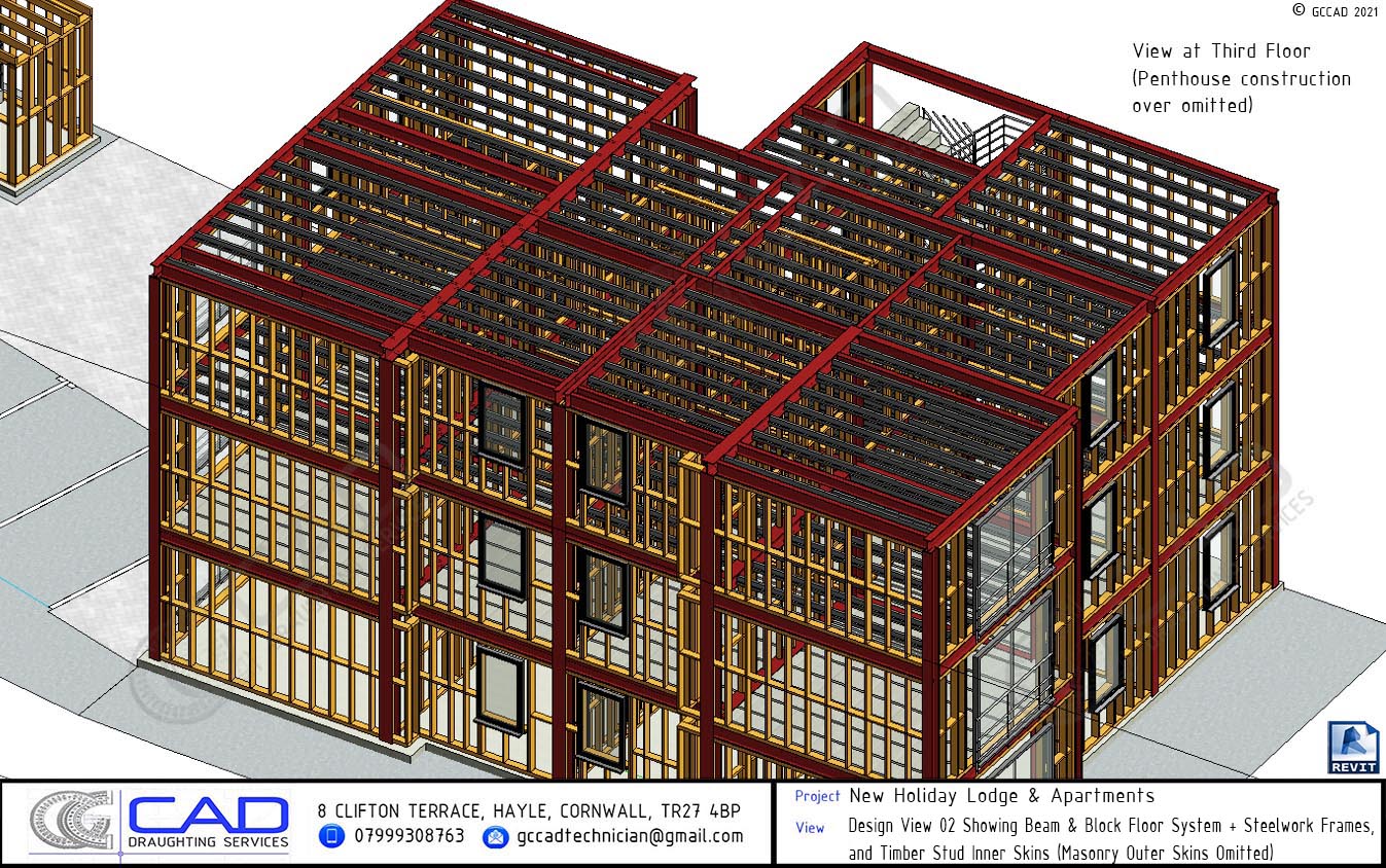
All key structural elements are present and precisely detailed in the model, including the steelwork frame, beam & block floor systems, flat roof joists and rafters, masonry outer skins and timber studwork inner skins. Foundations were omitted from this model as they were provided on a 2D plan at a later date in conjunction with the structural engineer.
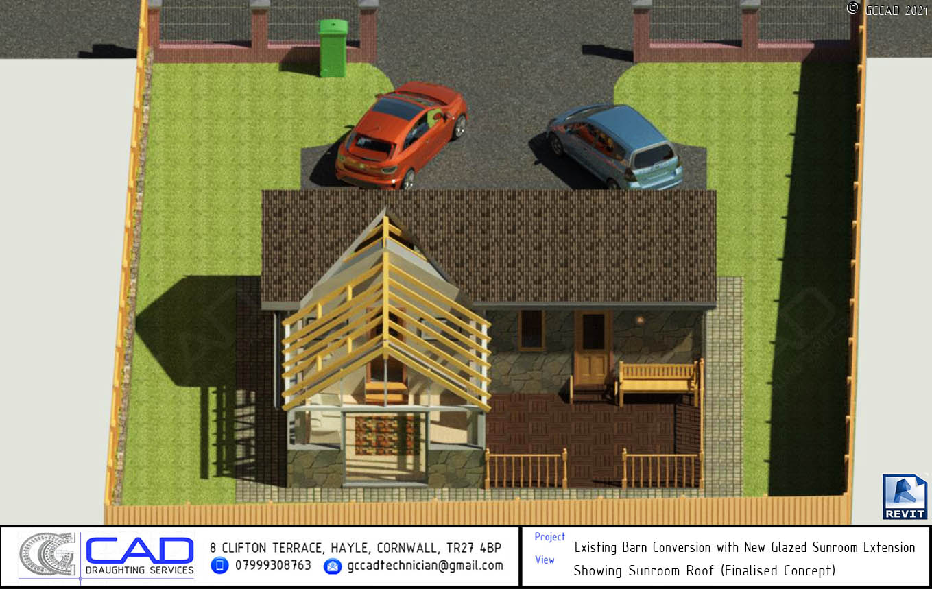
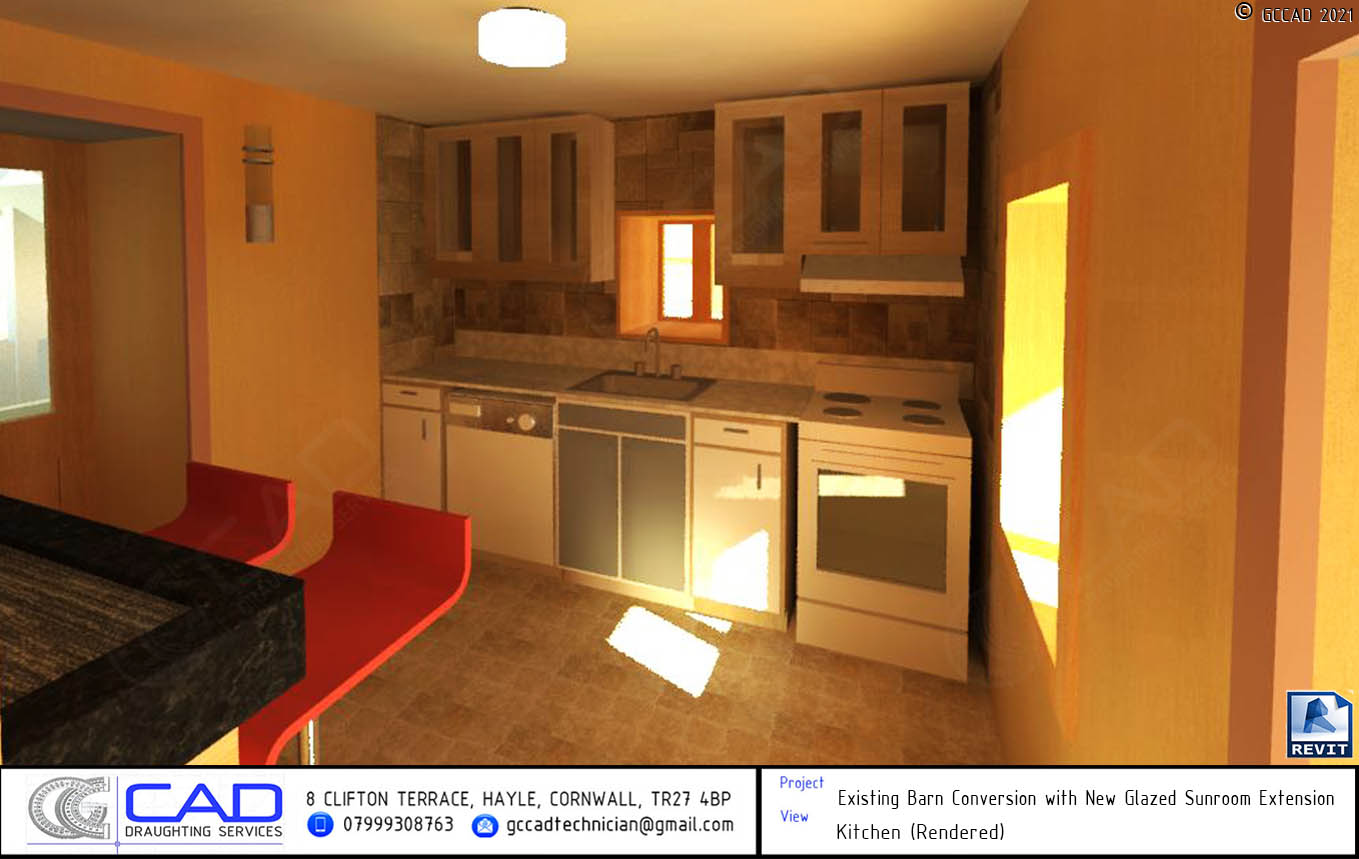
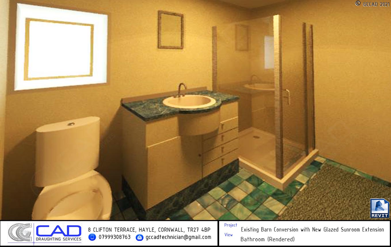
REVIT Project Example No. 2: Barn Conversion & New Glazed Sunroom Extension


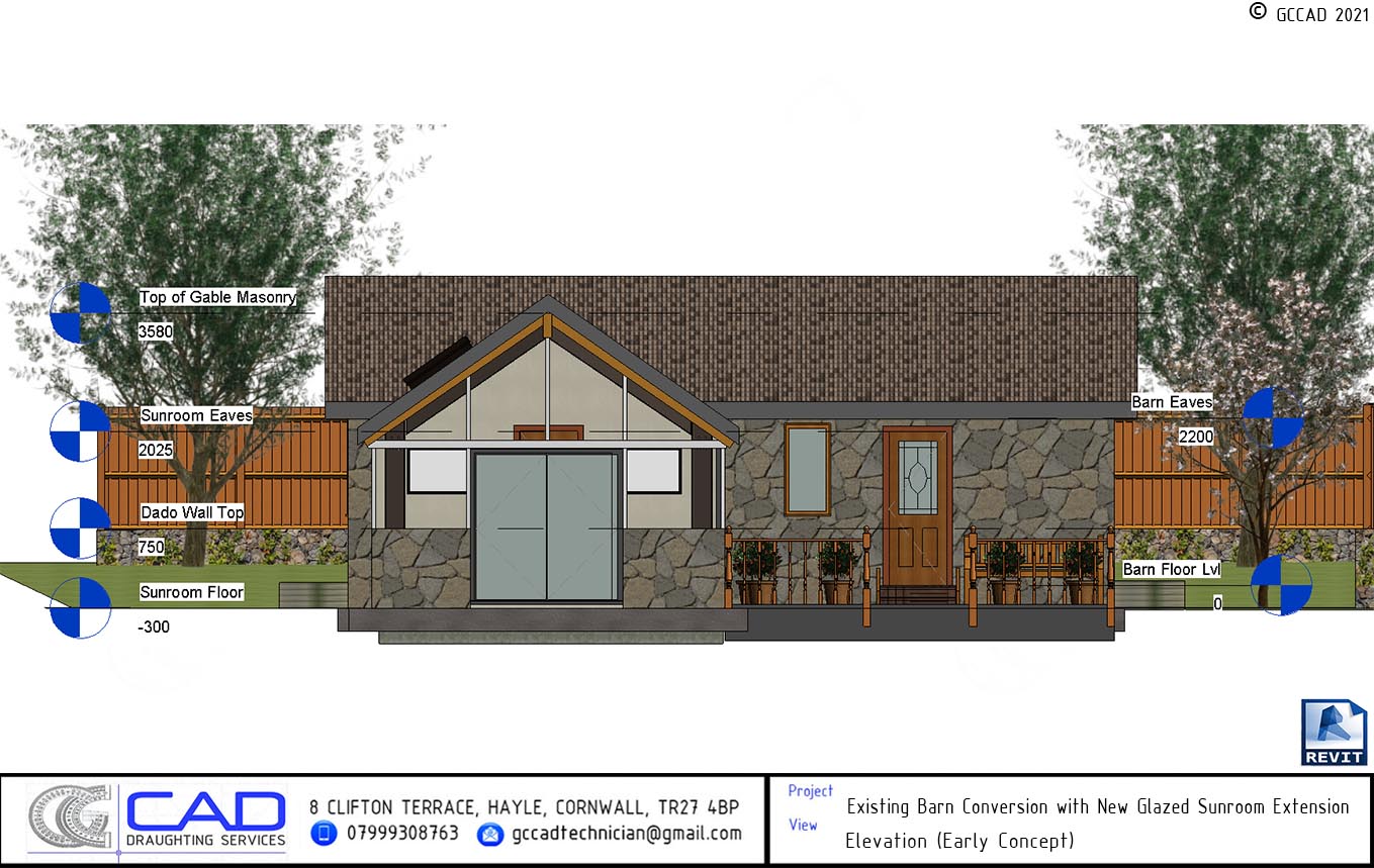
Glen modelled this lovely barn conversion project in the heart of West Cornwall. This disused barn went through a stunning transformation and was repurposed as a summer home, with the potential to be rented out as a holiday let. The existing space was used efficiently and a new glazed sunroom extension was added on the side of the barn.
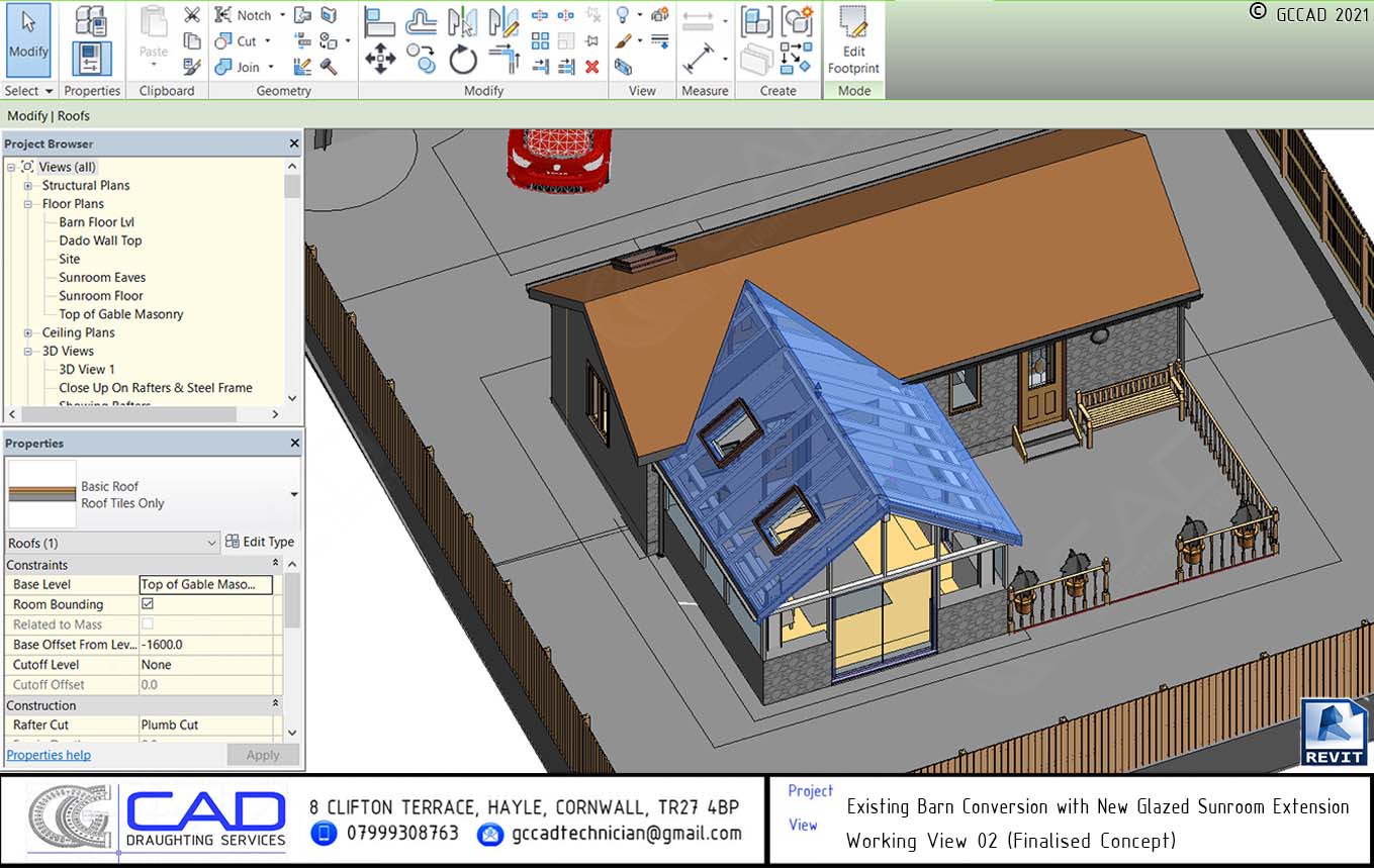


The existing barn’s sheet roof and timbers were replaced with a new 225 x 90 glulam ridge beam and 100 x 50 C16 rafters & ceiling joists at 600 centres. The original stone walls were lined with an additional skin of 100 x 50 C16 studwork and an insulated cavity, with double 100 x 50 C16 lintels over new and existing openings. 100 x 50 C16 internal studwork partitions were formed to create the kitchen, bathroom and bedroom.


The sunroom extension was an entirely new construction comprised of dado walls (100mm blockwork inner leaf, 100mm stonework outer leaf, 100mm insulated cavity, tied together with Ancon SPS x 250mm ties). A 254 x 102 x 28 UB steelwork portal frame was constructed with 140 x 140 x 5 SHS eaves beams. A 315 x 115 glulam ridge beam was specified and 125 x 50 C16 rafters were added at 600 centres, which were doubled up either side of the two new Velux rooflights. The glazing and oak framing were designed by others but GCCAD added an example frame to the model for indicative purposes. GCCAD also added indicative details for internal finishes, as well as the new timber decked sitting area outside.
Q: Can you clarify what file formats you use for your 2D drawings?
A: Typically, 2D drawings are provided (to an accurate scale) as industry standard formats: either .PDF, .DWG or .DXF files.
Q: Can you clarify what’s included in your 3D drawing packages?
A: At GCCAD, we understand that every project is different. Some clients may only need a 3D render or two, whilst others might require a more comprehensive package, therefore our deliverables are customisable to suit each client’s needs and budget. We will discuss this with you before you instruct us to commence work (a quote for each service will be provided in writing). We can provide 3D models in BLEND, IFC, DAE, FBX, or OBJ formats. From the native Blender model, we can export further 3D deliverables. We can include fully textured plans (top-down or isometric) for each level of the building, elevation(s) of the proposed works, and section(s) through the proposed works (all to an accurate scale in PDF format). Please note: We only provide “as existing” plans, sections & elevations if we are specifically instructed to by the client, as this requires another separate 3D model to be built (at further cost). Here is a recap of the customisable 3D options we provide (please refer to our portfolio for examples of all of the following):
- The native 3D model in Blend format (or converted to DAE, FBX, or OBJ).
- Data-rich BIM IFC models (this is a different process to standard 3D models and would be quoted for separately).
- Fully textured plans (top-down & isometric) for each level of the building (to an accurate scale in .PDF format).
- Elevation(s) of the proposed works (to an accurate scale in .PDF format).
- Section(s) through the proposed works (to an accurate scale in .PDF format).
- CGI renders of the project from different viewpoints. We typically provide renders either as an individual .JPG files or as multiple images on a drawing sheet(s) in .PDF format. Please note: All of GCCAD’s 3D models are constructed to accurate proportions (based on information received from the client), but typically 3D images are not considered to be at any specific scale; rather they are zoomed in or out accordingly and rendered at whichever scale is required for each image. Upon specific request however, it is possible for us to provide images on a drawing sheet (.PDF) to an approximate scale (e.g approx 1:10, 20, 50, 100 etc).
- A walkthrough / flythrough video of the project.
- A stand-alone, interactive “simulation” which allows the client to walk or fly through the model themselves using their computer mouse and keyboard as controls (requires a modern, graphically capable PC to run).
To reiterate, all of these options are customisable. You can mix-and-match any of the services you require from any of the packages (both 2D & 3D) and we will provide a fee quote based on the total amount of work required to meet your needs. When both parties have agreed on the proposals in writing, GCCAD will commence with the work.
Q: Can you provide more information on your native 3D models?
A: GCCAD’s 3D models are built using Blender, an extremely powerful piece of open-source software developed by the Blender Foundation and supported by a dedicated online community. Blender has, for some time, been a powerhouse in the animation and video game asset creation scene but has in recent years come on leaps and bounds in Architectural Visualisation / BIM, too. GCCAD has mastered the software’s steep learning curve in order to create impressive 3D architectural environments. There are no license fees for Blender; it was designed purely with content creation in mind. This allows GCCAD to keep our overheads down and, crucially, charge our clients less. This simply would not have been possible a few short years ago but technology is constantly evolving and GCCAD aims to be at the cutting edge, offering our clients a stellar service at a competitive rate.
To open .Blend files, our clients will need to visit the Blender website and download the software executable (this is completely free of charge as the software is open-source). The program doesn’t require you to have any special training to just view GCCAD’s 3D models; it’s straightforward enough for the layman, and anyone experienced with other 3D software programs such as Revit, Sketch-Up etc should be right at home.
Please note: for first-time clients we may kindly ask for payment to be completed up-front, before the 3D model is delivered. This is a necessary step to help protect our work as 3D design is a highly complex and time-consuming process. Alternatively, on especially large ongoing projects, a series of milestone payments would also be acceptable.
Q: Can .blend files be opened in Revit, or do you provide an alternative format that can be?
Blender files (.Blend) and Revit projects (.RVT) are not interoperable, but thanks to Open-BIM standards we can communicate with other industry professionals using the open IFC (Industry Foundation Classes) format. These files can be easily opened and interrogated using a free IFC viewer such as BIM Vision. BIM authoring software such as Revit or Archicad also feature IFC open / link functionality; however, GCCAD’s models have not been tested using these processes, and therefore we cannot guarantee success therein. It’s worth noting that modern software is constantly evolving and we are hopeful that cross-software compatibility will improve in the future, allowing us to share models between different software packages more freely. For now though, the optimal way to view or interrogate GCCAD’s 3D models is within Blender, and our IFC’s within BIM Vision (or a similar free BIM viewer).
GCCAD can also export standard 3D models (non-BIM) in a range of formats (FBX, DAE, OBJ) which may potentially be importable into your CAD or BIM software package (please consult your software’s manuals or technical support service).
Q: Can you clarify what information you need from your clients in order to create your 3D models?
A: As long as it’s dimensioned or drawn to scale, GCCAD can generate a 3D model from a simple sketch. Of course, the more information you can provide us with, the more detail and accuracy we can put into the model. A set of architect’s drawings would be ideal for our purposes, specifically: floor & roof plans for setting out information (including floor-to-floor & floor-to-roof heights), and elevations so that we can get a feel for how the building should appear from the outside. Though not essential, a section(s) would be very helpful to determine floor heights, and a specification of materials & finishes would also be helpful when it comes to applying the correct textures to the model.
If your project is an extension of a currently existing building, photographs of the existing construction would also be a useful resource to help us to digitally recreate the building. This could include: photographs of all elevations of the building & boundaries to adjacent or attached properties (if applicable), and internal photographs of all the rooms in the house (if you wish to have a high level of internal detail present in the model).
Q: What should I do if I don’t have a set of architect’s drawings?
A: This would be a fairly unusual scenario; if you’re seeking planning permission for your proposed project then you will need to be in possession of an ordinance survey plan, a site plan, elevations and floor & roof plans, which would typically be drawn by an architect, engineer, technologist or similar construction industry professional.
But what if you haven’t gone in for planning yet, or have no desire to in the near future? Maybe you're just showing off a concept to interested parties? Perhaps you just want a 3D model created of your own house? GCCAD would request in these instances the following information, in order to create an accurate model:
- A written description of the proposed works (if any).
- Photos of all external elevations of the building (if existing) and of boundaries to adjacent or attached properties (if applicable).
- Internal photos of all the rooms in the house (if you wish to have a high level of internal detail present in the model).
- External dimensions of the entire building (the footprint of the building).
- Internal dimensions of each room.
- External & internal wall thicknesses and construction type, if known (i.e blockwork, timber stud, etc).
- Window opening widths and heights (including measurements from finished floor level to the window sill, and finished floor level to the window head).
- External and internal door opening widths and heights (unless your internal openings clearly vary, measuring just one existing opening should suffice).
- Floor-to-floor (or floor-to-ceiling) heights of each level.
- Height from existing ground level to ridge (alternatively, a measurement from the attic joists to the underside of the ridge).
- (If applicable, for all levels) Depth, centres and span of any exposed floor joists.
- Details of stairs (if applicable): count risers and take a photograph from top of flight looking down and vice versa. Height of each rise. Width of each going. Determine overall height of stairs by measuring lower floor to ceiling height + higher floor thickness.
- Full postal address of the property.
Note: Please be assured that GCCAD will never share any of the information you provide with a third party without your permission.
Q: You mentioned that minor changes are free of extra charge - can you clarify?
GCCAD has several years of experience working within design offices and understands that a project goes through many phases, such as design, drafting and then checking. Whilst the checking phase is perhaps more convenient in an office-based environment, and that further coordination may required to ensure this stage goes smoothly with remote-based working, GGCAD does not expect to be presented with every last piece of information at the first time of asking. The design process is back-and-forth in nature. After the initial submission of our work, we would expect that further additions, corrections or amendments may need to be implemented before the drawing is up to issuable standard. These are what we would consider to be part of the initial fee, and provided they are brought to our attention within a reasonable time-frame after our original submission, we would not charge for them.
Major amendments, such as changes to the original design or a series of smaller alterations, would be chargeable at our standard hourly rate. It all depends on the amount of extra work that we would be required to undertake. A few alterations to a 2D plan may only take an hour but the same changes on an already built 3D model could take several times longer.
Q: After the initial work has been submitted, how would I advise you of any amendments that are required?
There are several ways. You could send us a quick email advising of the changes that need to happen. For more advanced users, you can use Adobe Acrobat Reader to add sticky notes to our PDF drawings where changes are required (easy guides are available on the internet to help with this). You could also take a paper print-out and quickly mark on in pen the information that you need adding. Take a photograph or scan of the marked-up print and email it over to us at gccadtechnician@gmail.com. Alternatively, you could take a “print-screen” capture on your PC and mark it up digitally using an image editing program such as MS Paint.
Q: Do you only work with clients based in Cornwall?
Our offices are based in West Cornwall but GCCAD offers a nationwide service. Advances in technology have made remote working a genuinely viable alternative to office based work, and as such we are capable and more than happy to work with clients from all across the UK.
need to contact US?
Should you wish to discuss your project requirements with us, or just wanted an informal chat about any queries you may have, we'd love to hear from you. Please choose any of the contact methods below, and thank you for your visit!