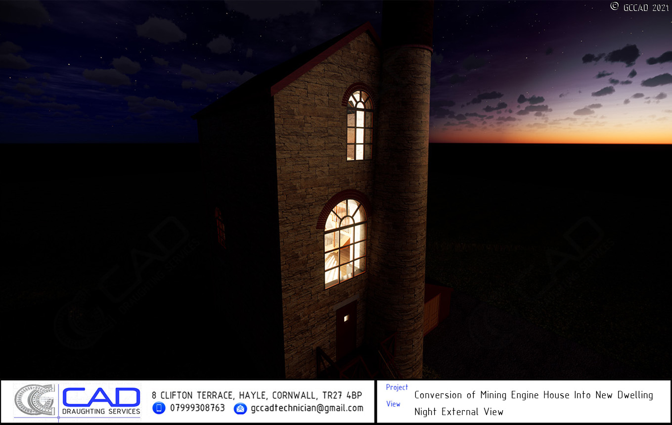
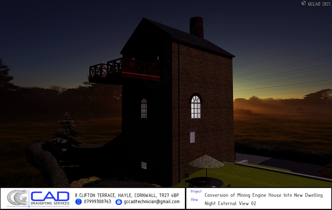
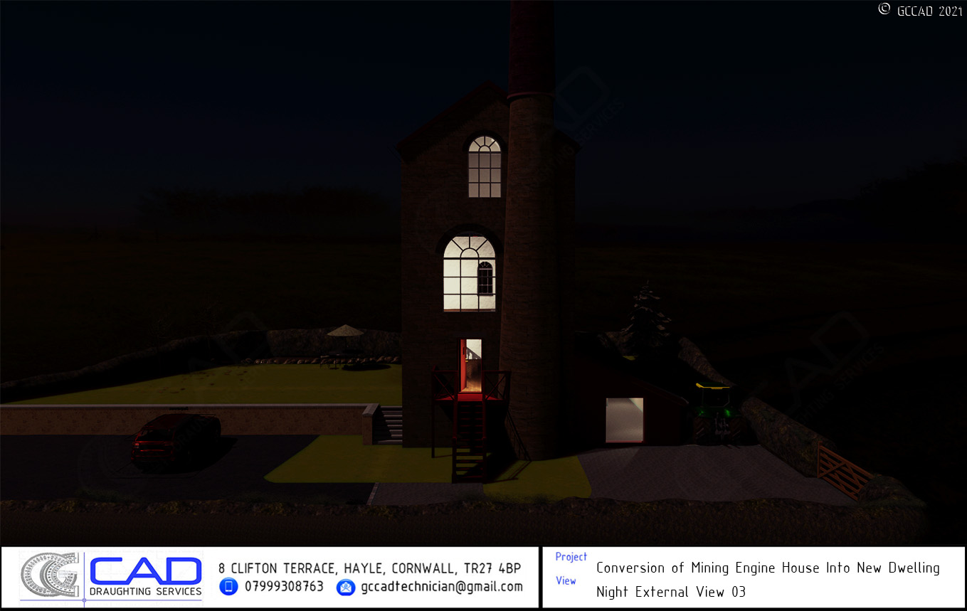
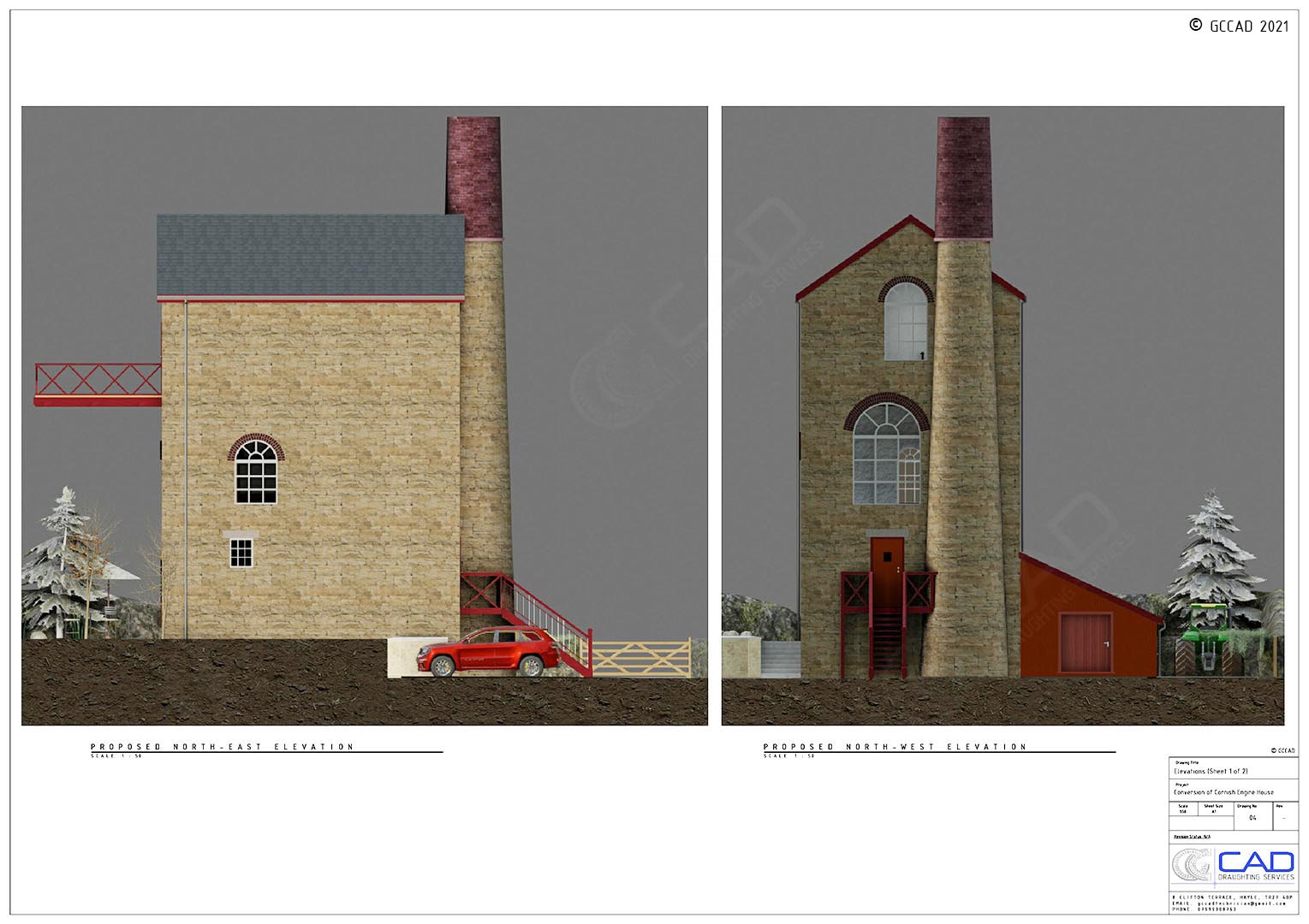
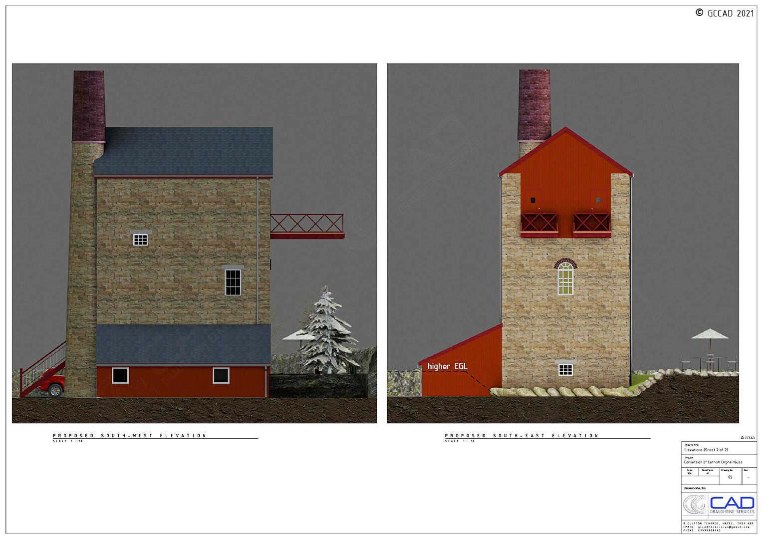
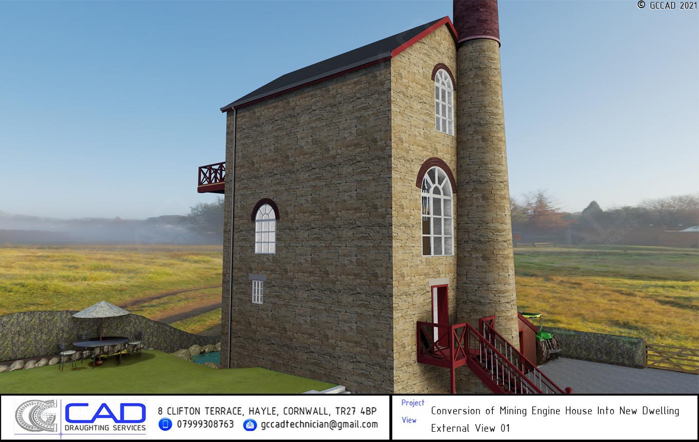
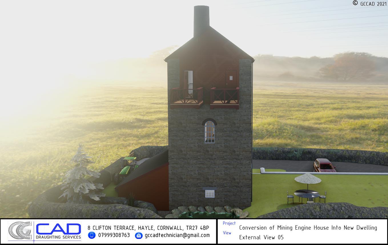
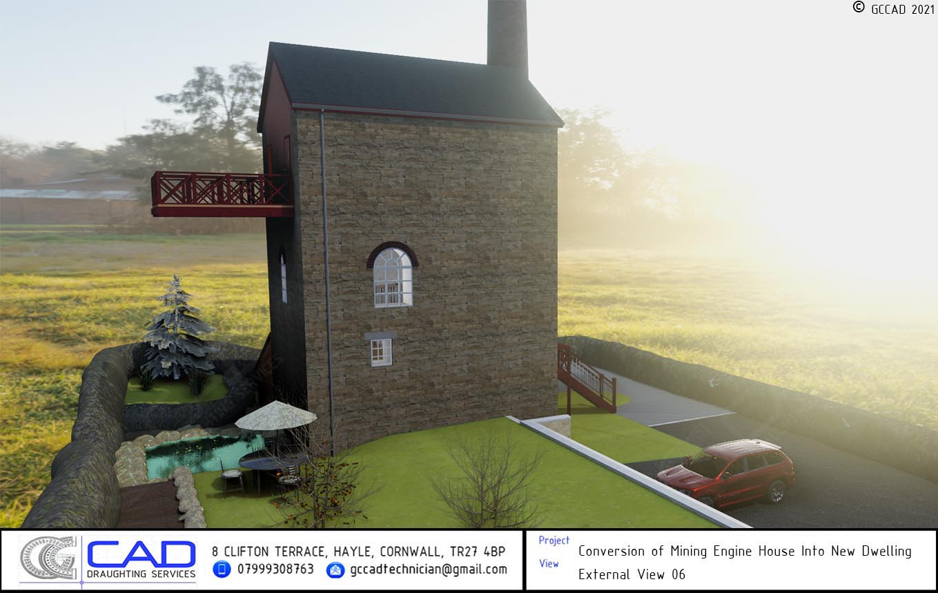
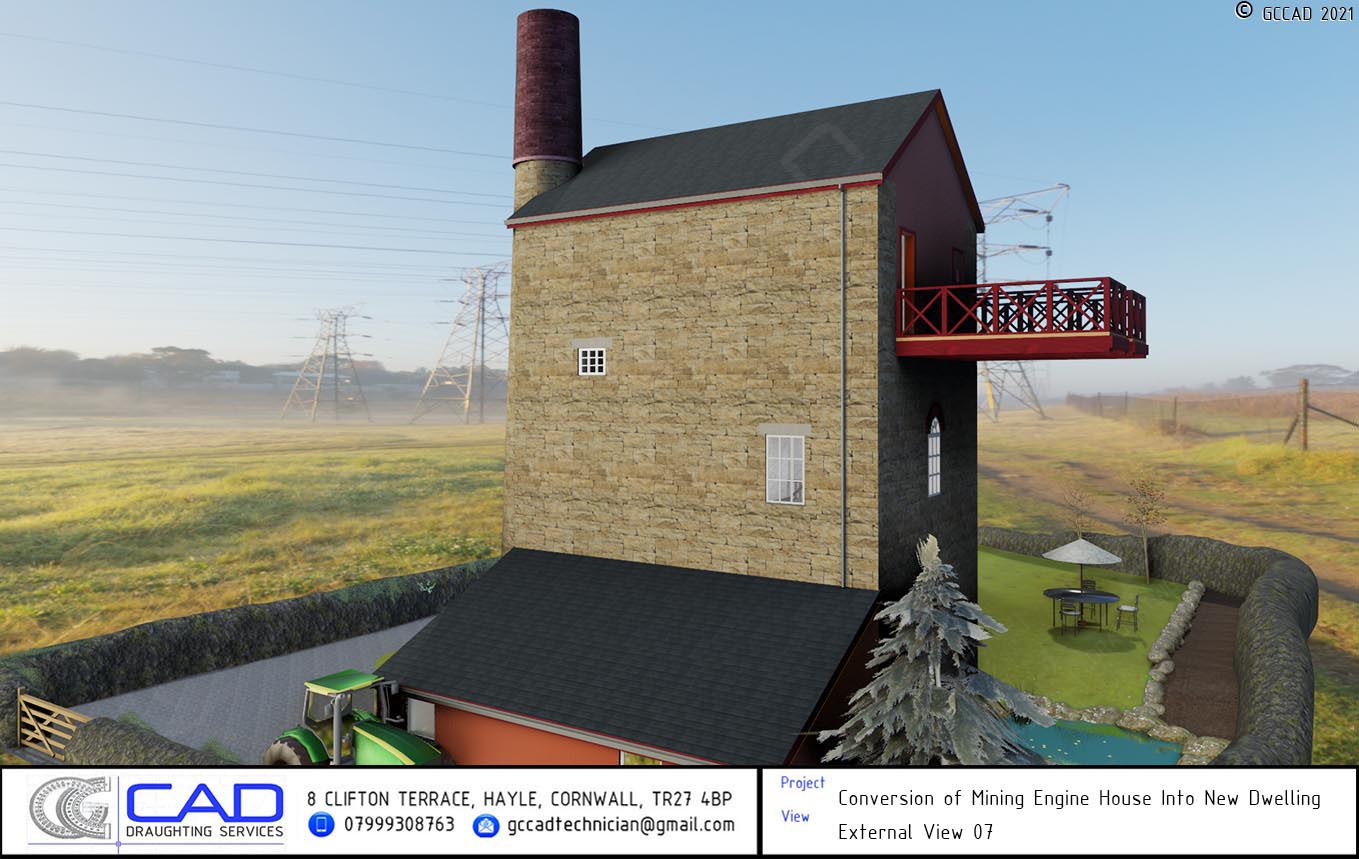
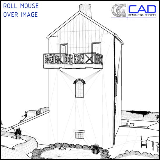
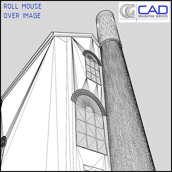
GCCAD worked on this unique conversion of an old Mining Engine House to a new dwelling, situated in the stunning Cornish countryside. Planning permission is difficult to obtain on historically sensitive buildings such as this, so participating in the design work on the project was a fantastic experience and a chance to demonstrate our stellar 3D services. A strict condition of planning approval was for the exterior to be restored as it was originally constructed during the prosperous past of the Cornish tin mining industry. Alongside the 3D model showcased here, a full set of 2D structural plans and details were also produced by GCCAD. Please enjoy the video walkthrough above (fullscreen recommended for optimal viewing experience; video has been compressed for web playback), or click an image below to enlarge. Whilst viewing, click on the left or right of an image to navigate backwards or forwards respectively. Scroll further down the page for "sketch-to-realistic" roll-over images.
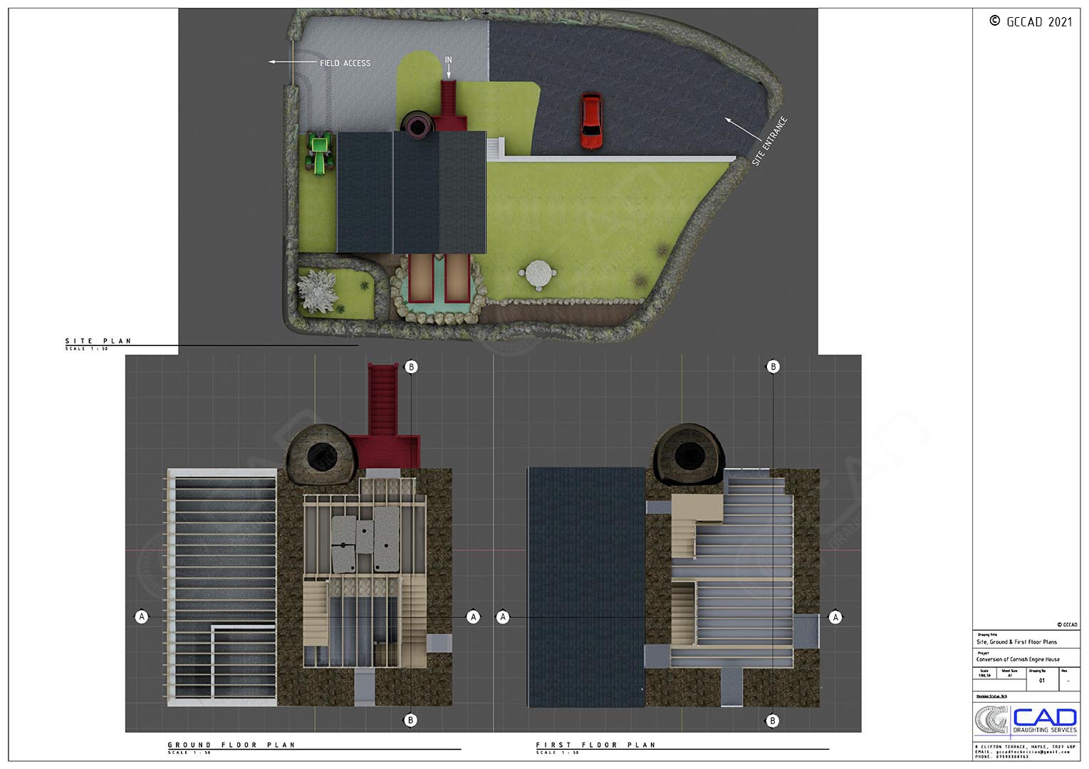
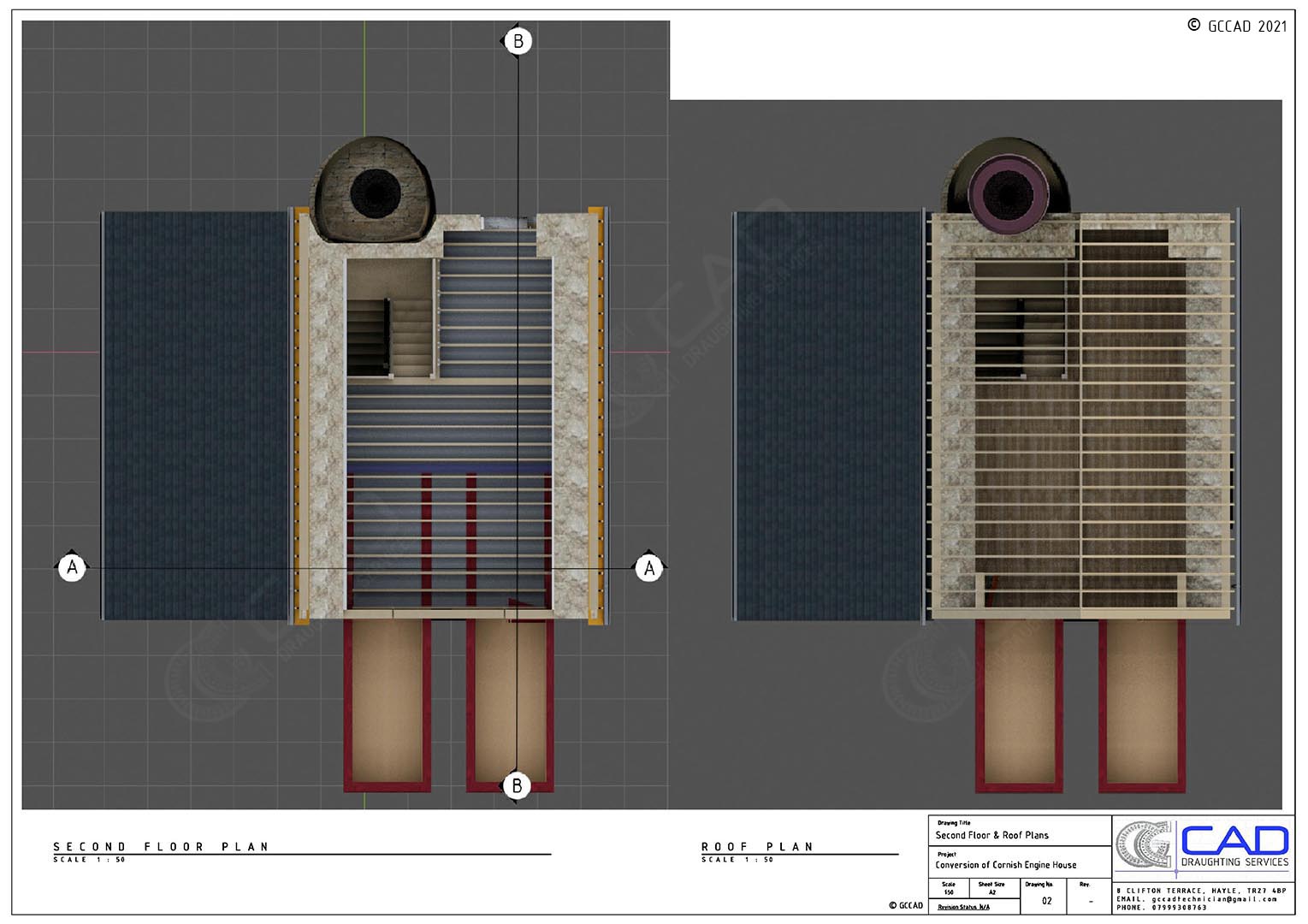
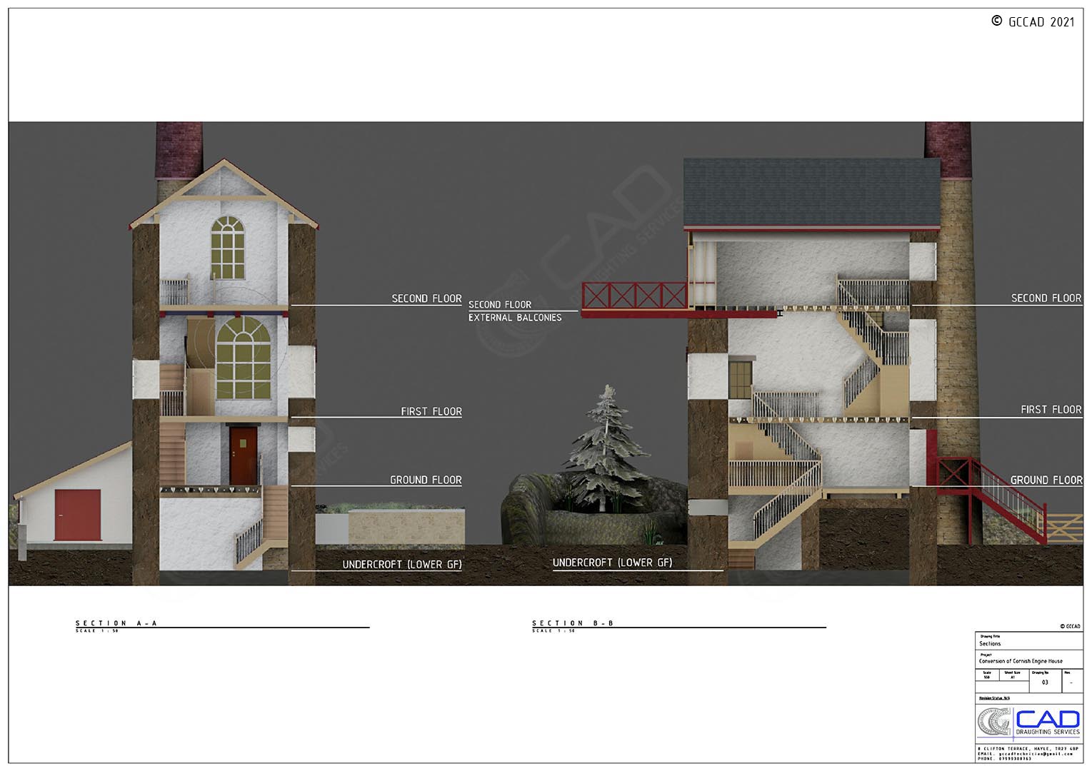
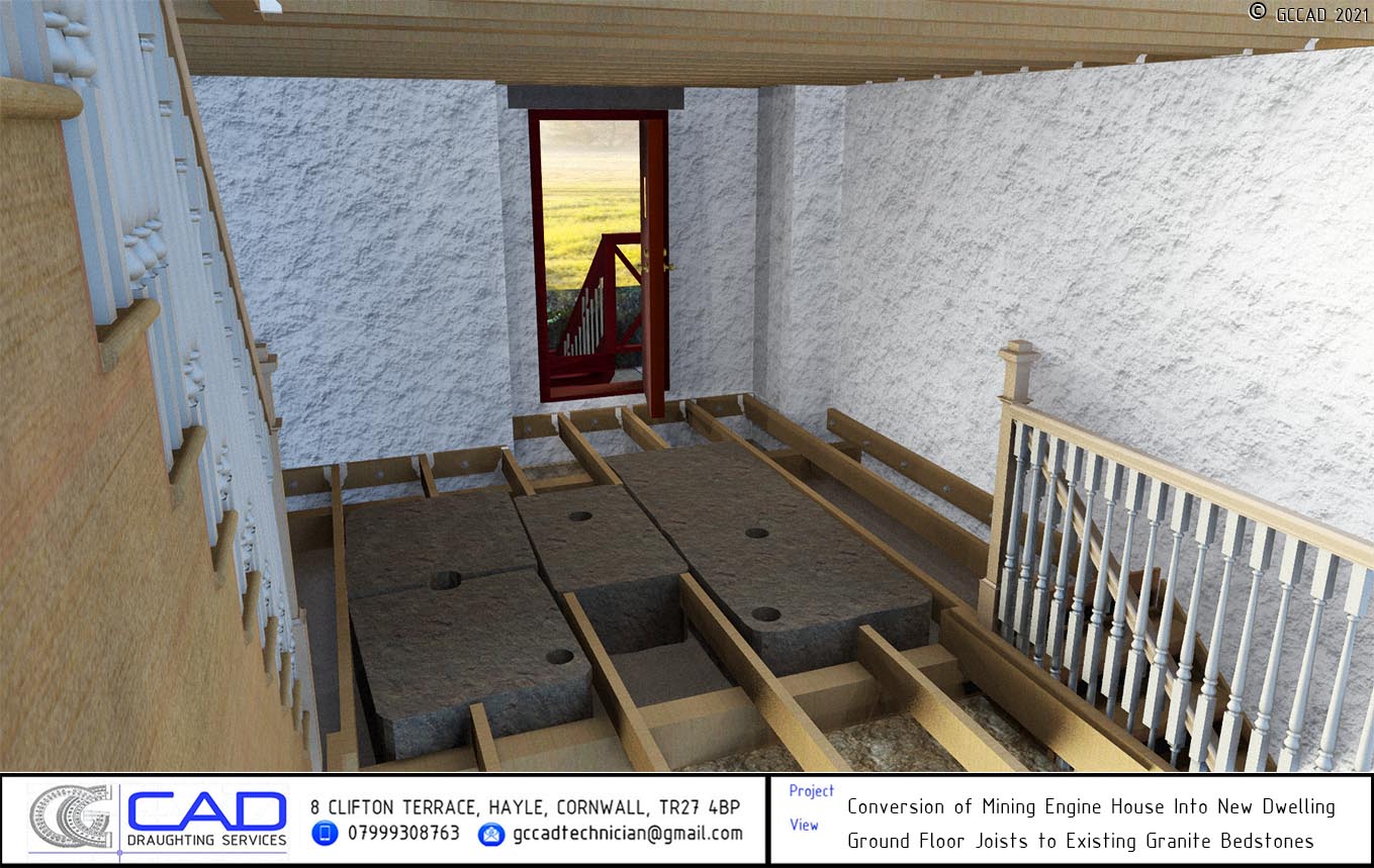
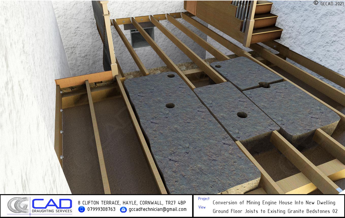
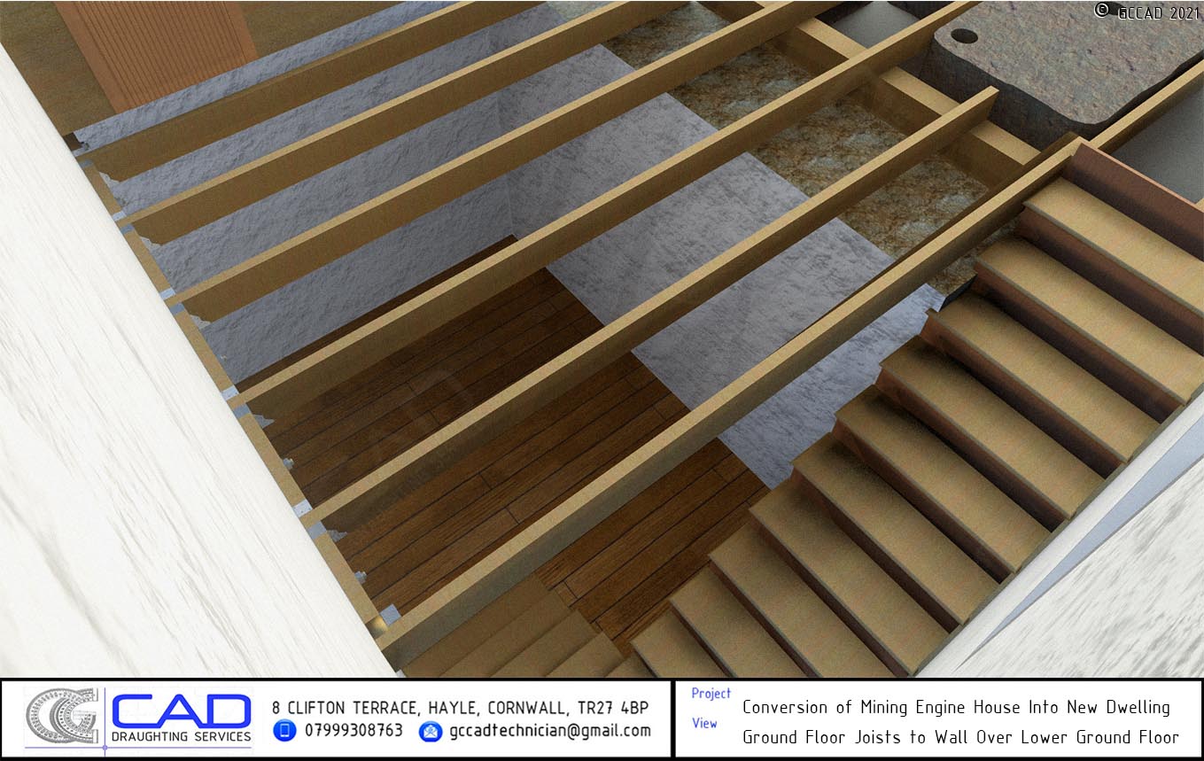
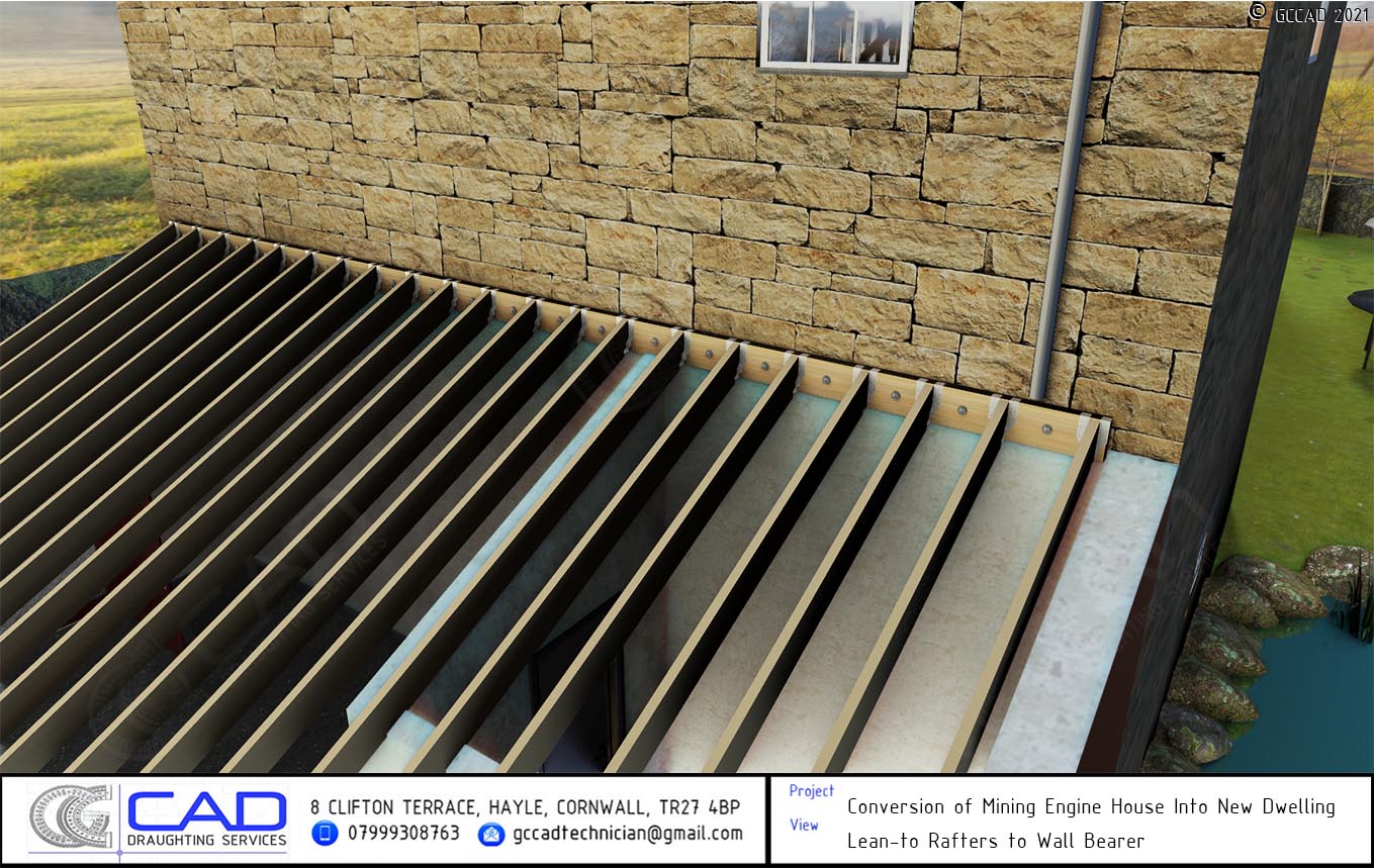
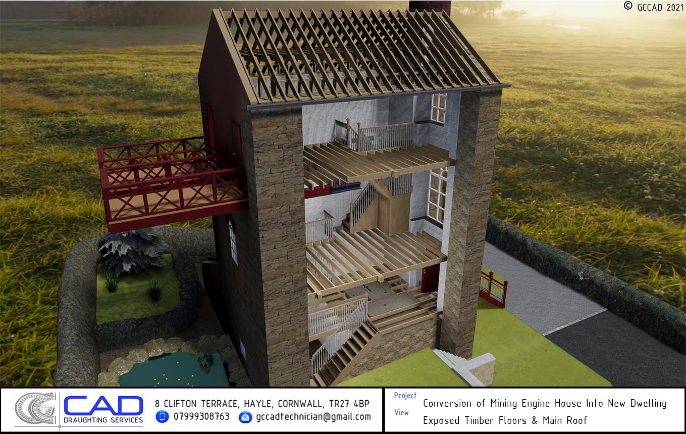
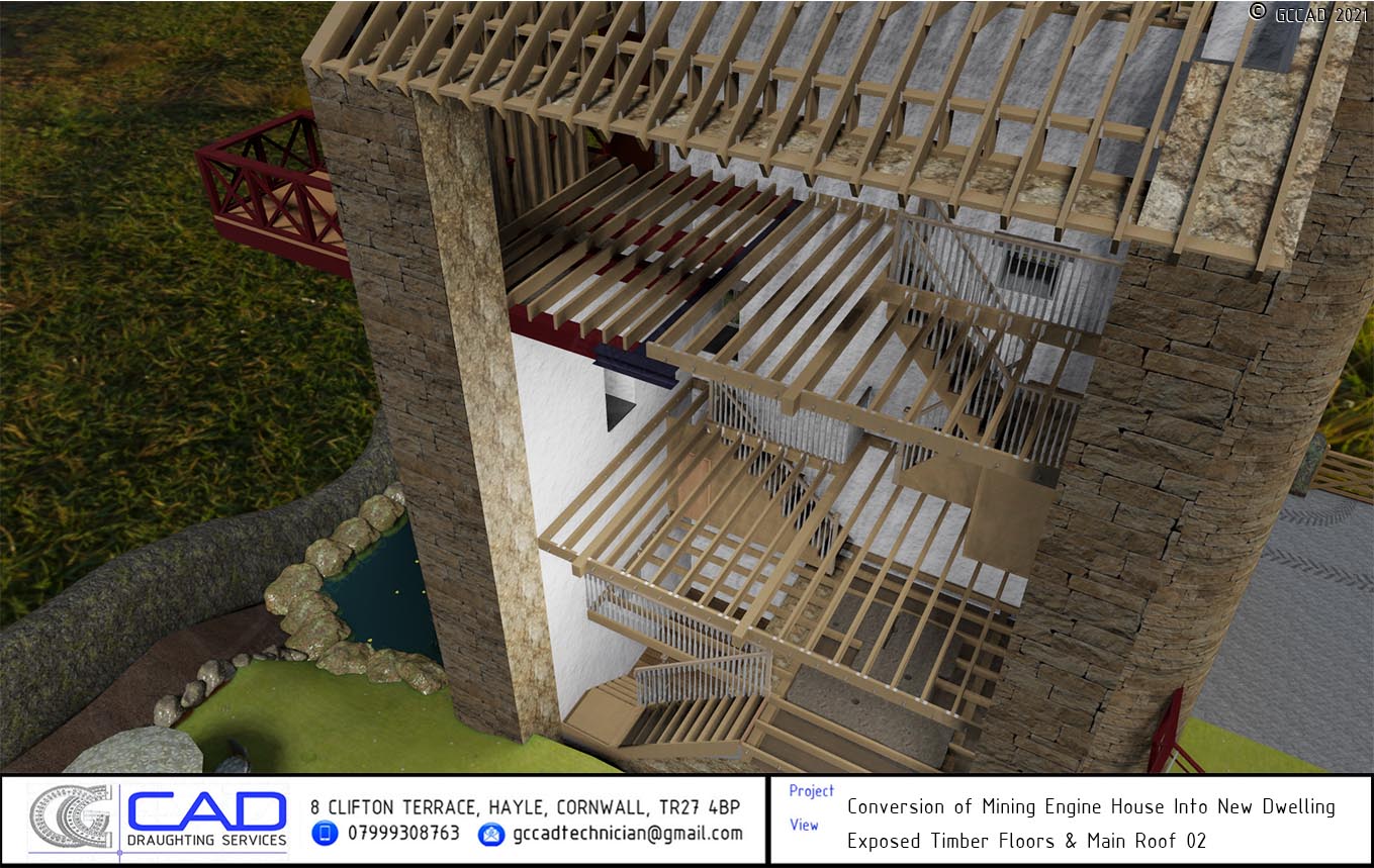
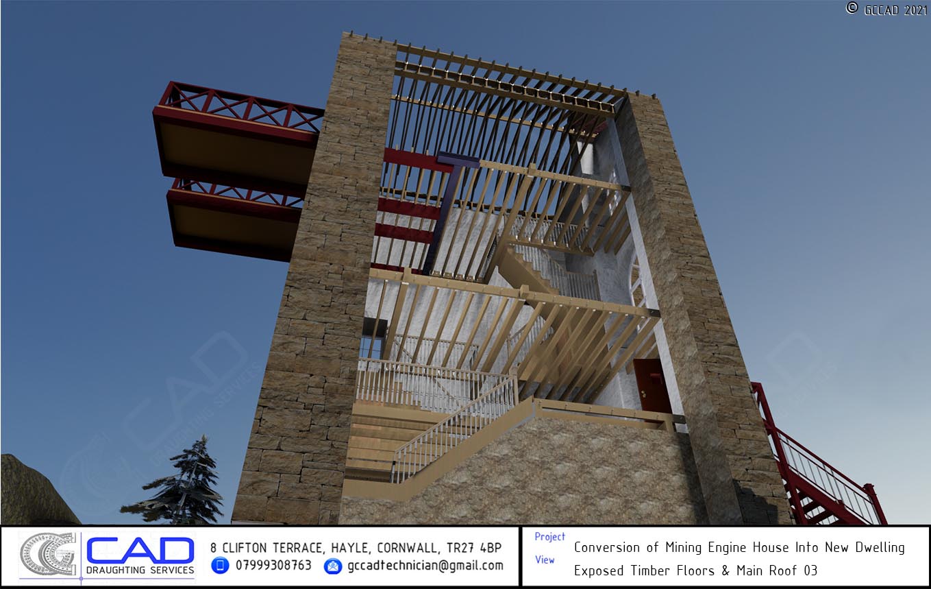
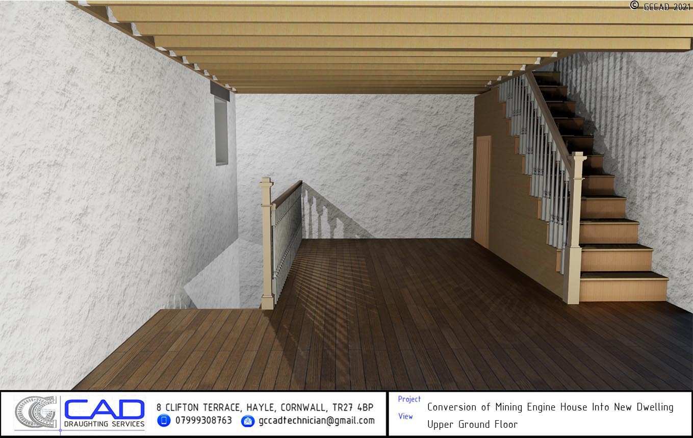
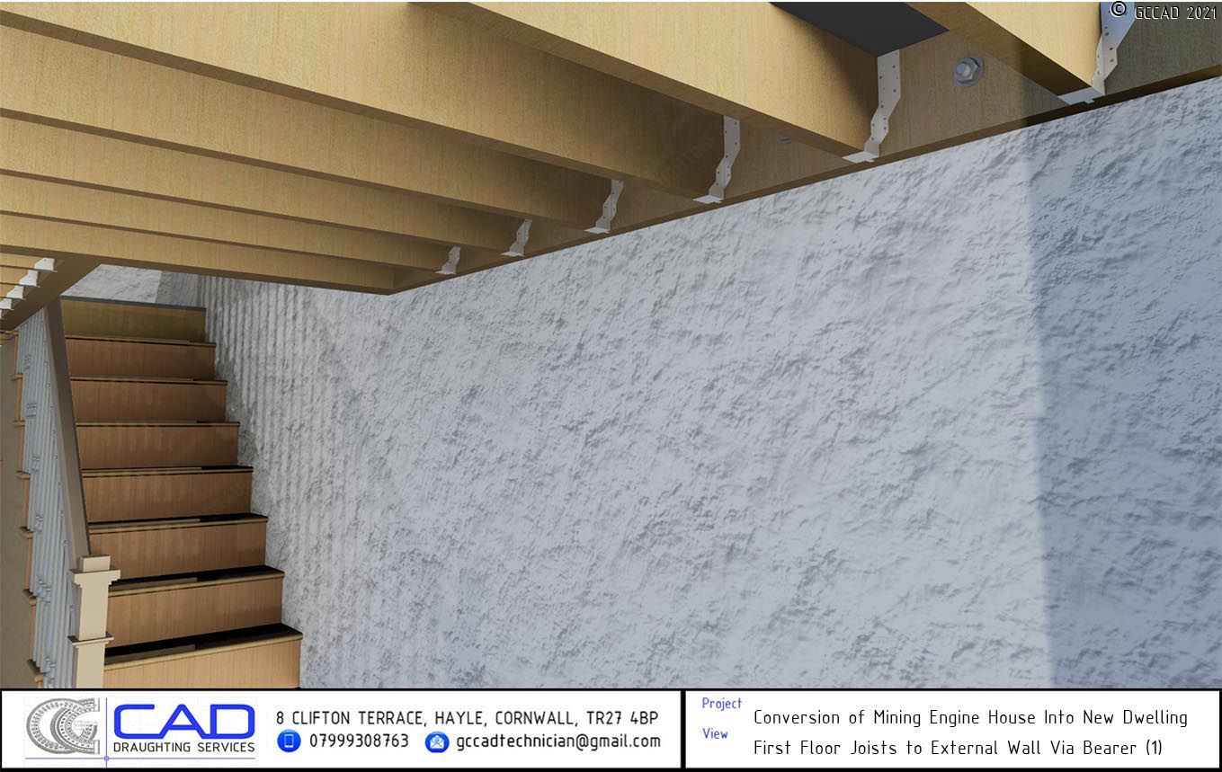
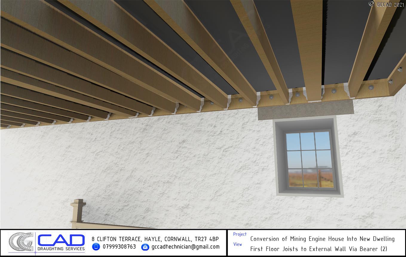
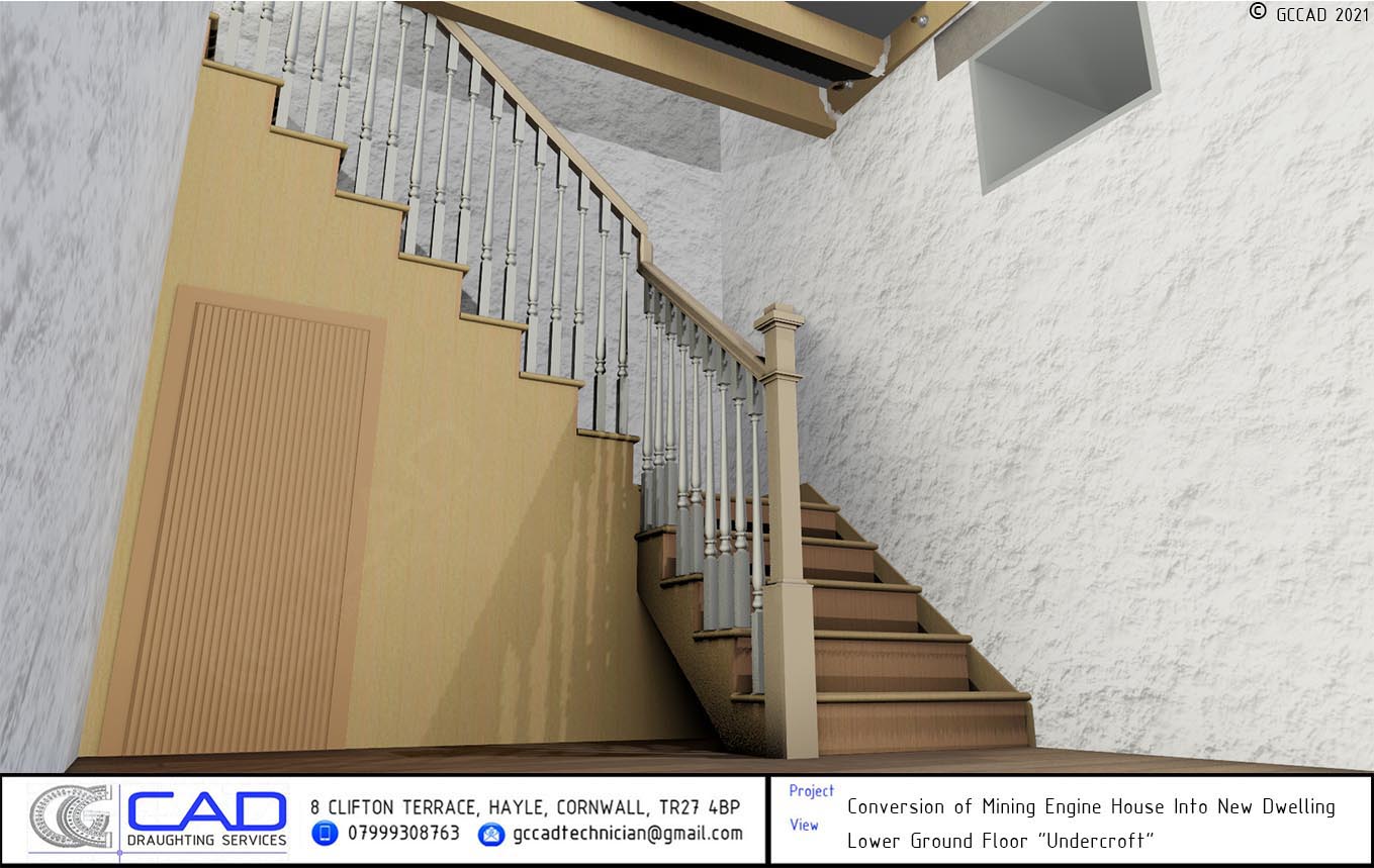
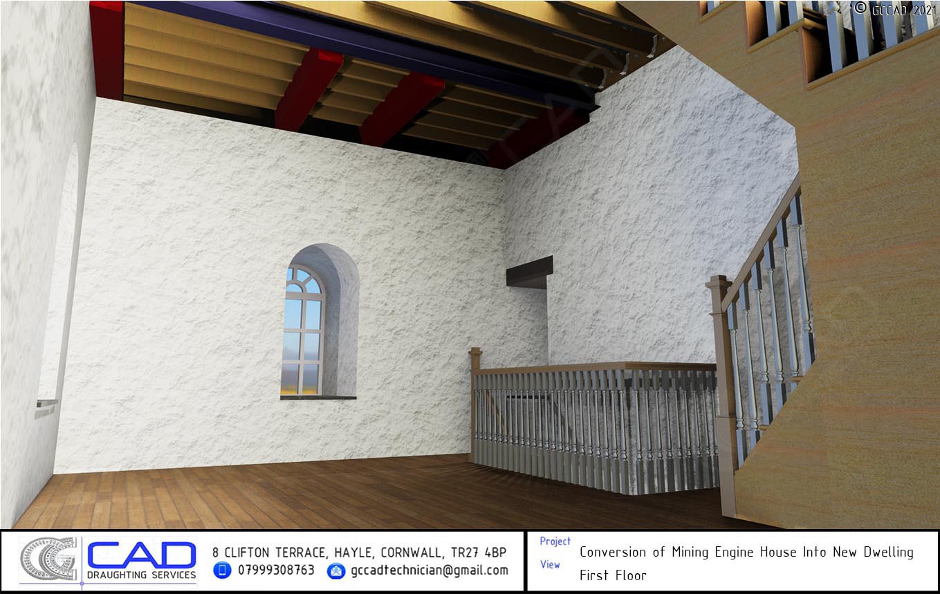
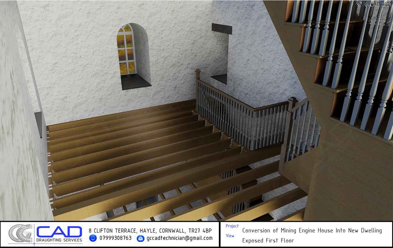
Internal partitions were omitted in GCCAD's model as they were yet to be determined and agreed upon by the client and architect. Our brief was to demonstrate the structural elements of the new construction. New floors were to be constructed at upper ground, first & second floor levels, comprising floor joists fixed to timber bearers resin anchored into the existing granite walls. At upper ground floor level, the joists would be constructed around existing granite bedstones, which were to remain, and a new staircase would be formed to access the lower ground floor "undercroft" storage area.
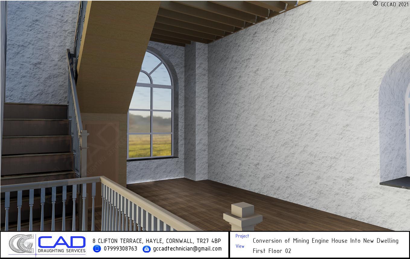
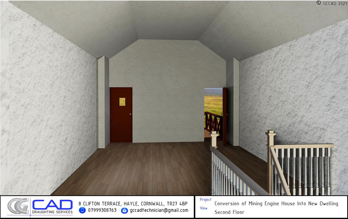

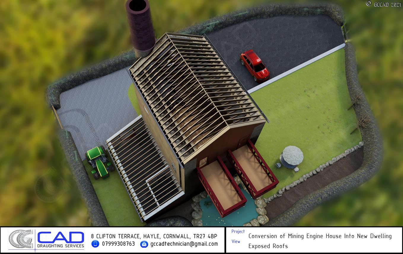
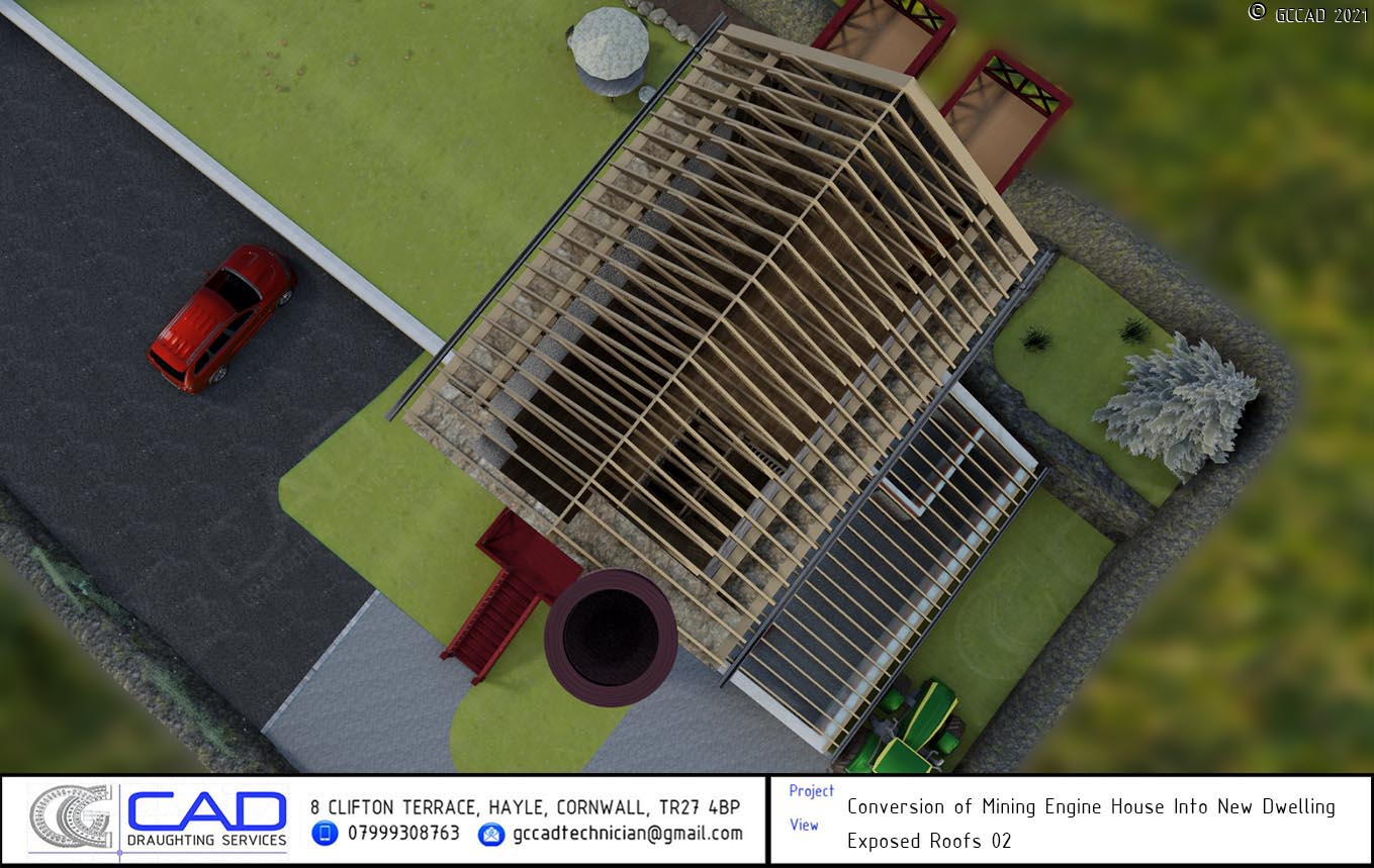
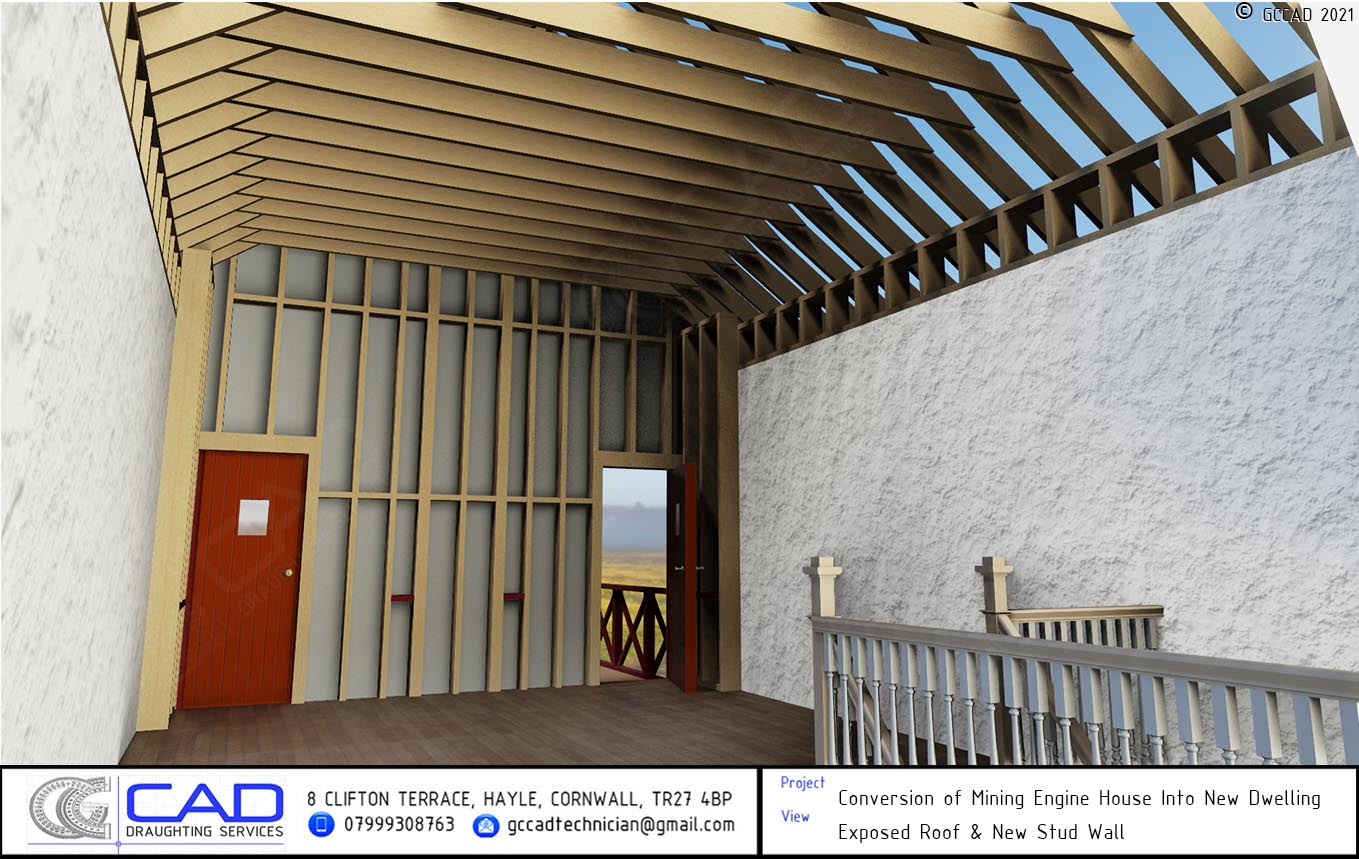
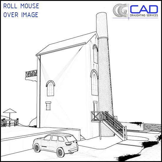
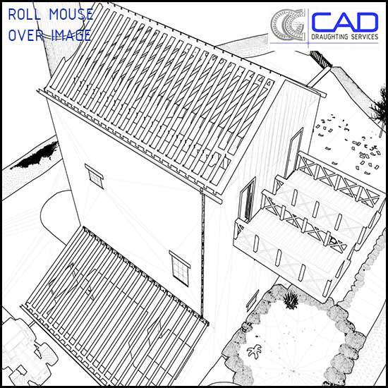
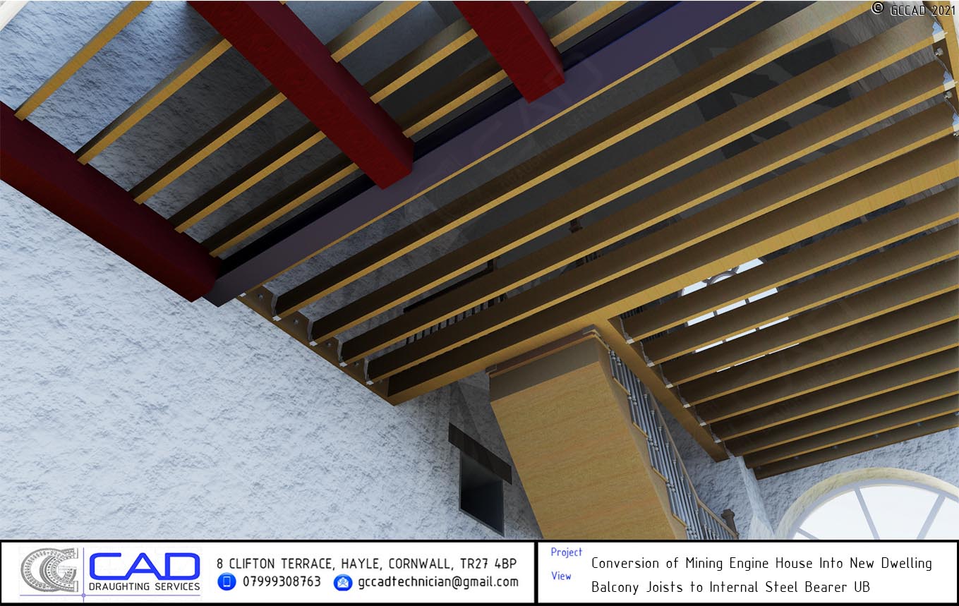
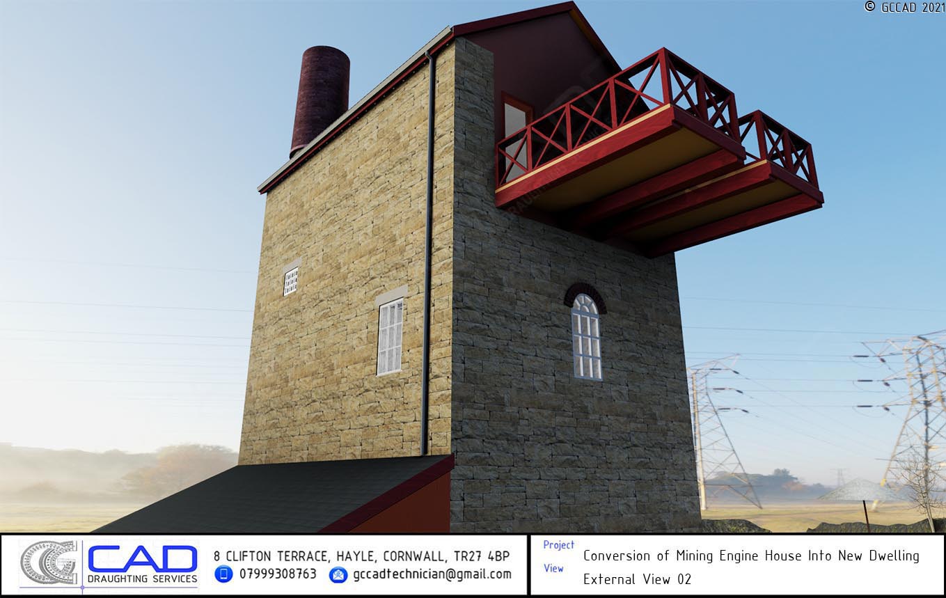
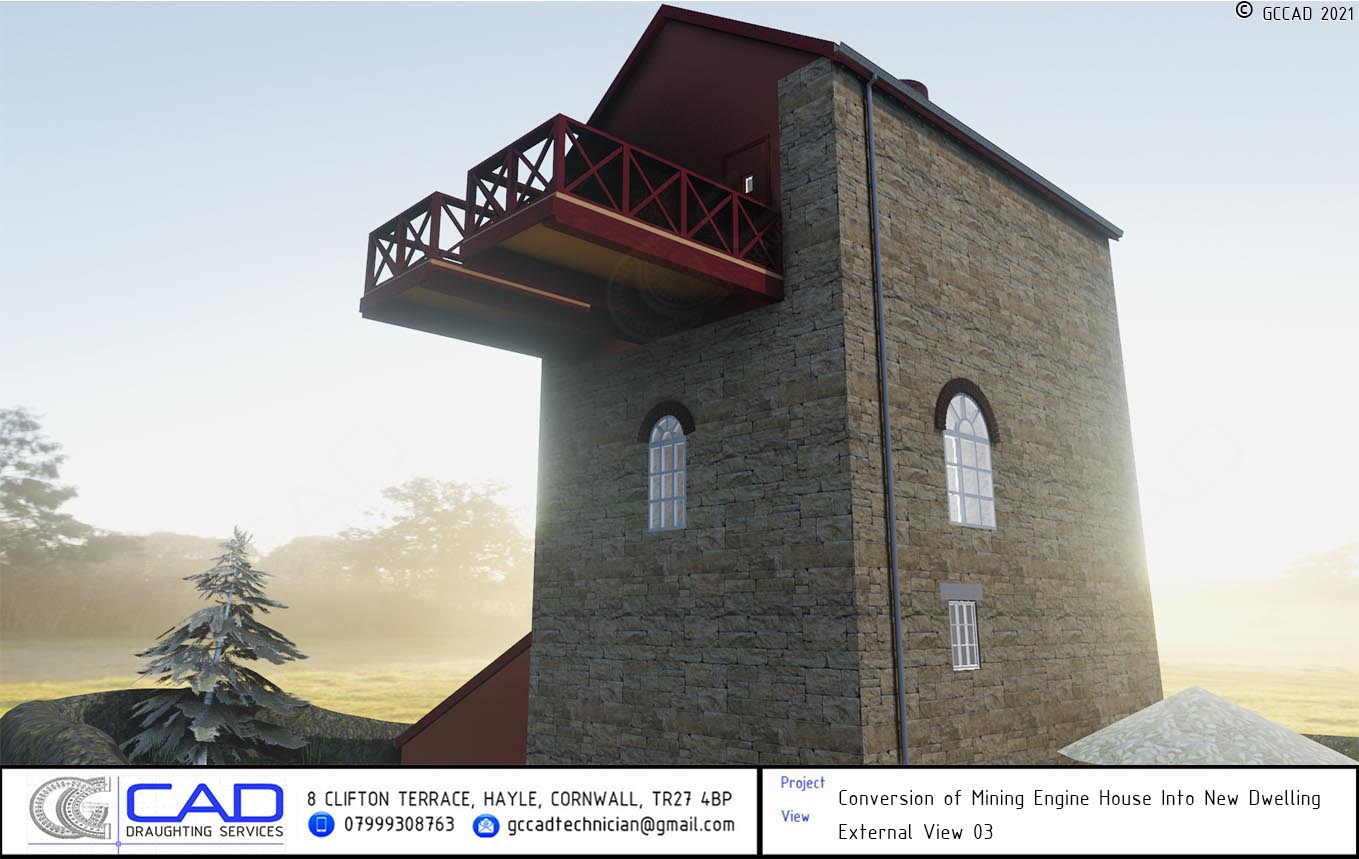
In agreement with the planning department, the use of steel members was to be kept to a minimum and concealed. At second floor level, two cantilevered balconies were formed comprising four 225 x 300 C24 beams. These beams – which were 7.3 metres long – were to bear on a reinforced 150mm deep x wall width padstone, cast into the top of the existing granite wall beneath where the pump-lever of the beam engine would originally have been. The beams were to then extend into the building, forming part of the second floor, until they met a 203 x 203 x 46 UC cross-beam in the floor zone, into which they were carefully profiled and fixed. The cross-beam was to bear on a padstone at one end and connect to a steelwork spreader at the opposite end above an existing arched window, thus transferring the loads from the cantilevered balconies into the existing walls. A new timber infill wall near the balconies was designed in 200 x 50 C24 studs at 400 centres, with mid-height noggins. Additional studwork was added to form boxing around the balcony handrails, which extended inside the building and were fixed to the existing wall using angle brackets and resin anchors.